Simultaneous Current and Voltage Output
The terminal block is removable and each of the terminals is labeled underneath the
terminal block on the circuit board. Positive polarity is indicated by VOUT. The VDC
terminal and a DC power supply must be used for simultaneous current and voltage
output. The voltage output and the power supply must have separate wire leads that
are only joined at terminal 2 of the transmitter. Additional error may occur for the
voltage output if a single wire is used or if the wires are joined at the power supply or
receiver.
For the current output, the maximum allowable loop resistance (wiring + receiver
resistance) is dependent on the power supply. The maximum loop voltage drop must
not reduce the transmitter voltage below 17 V. The maximum loop resistance (R
MAX)
for a given power supply voltage (V
PS) can be calculated using the following equation:
The equation uses 17.0 instead of 10.0 as seen in the equation earlier with Figure
1. This represents the minimum voltage supply which is higher on the simultaneous
output conguration due to the requirements of the voltage outputs.
Shielded 4-wire cable is recommended for control loop wiring. Ground the shield
at the power supply end only. Should the polarity of the transmitter or receiver be
inadvertently reversed, the unit will not function properly, but no damage will be done
to the transmitter.
For voltage outputs, the minimum receiver load is 1 kΩ. The resistance due to the
wire should be low compared to the receiver load resistance. While the voltage at the
terminal block remains unchanged with a 10 mA current ow, resistive losses in the
wiring do cause errors in the voltage delivered to the receiver. For a 1% accurate gage,
the resistance of the wires should be less than 0.1% of the value of the receiver load
resistance. This will keep the error caused by the current ow below 0.1%.
The output across VOUT and COM will be either 0-5 V or 0-10 V depending on the DIP
switch setting. See DIP Switch Settings Section for more information.
Power Supply
Refer to the following tables for the required supply rating.
DIP SWITCH SETTINGS
DIP switch settings are marked directly on the PCBA as shown in Figure 5. Switches
are factory-set, based on the order conguration. You can also use a small screwdriver
or pen to change the position of the switches.
Key To DIP Switch Settings
Switches are numbered 1 to 8 beginning on the left.
DIP Switches 1 and 2 - Unit of Measure Selection
DIP Switches 1 and 2 work as a pair to select the unit of measure.
VAC
VDC
COM
VOUT
DC POWER
SUPPLY
10-36 VDC
VOLTAGE
RECEIVER
CURRENT
RECEIVER
+-
+ - +-
Figure 4: Simultaneous current and voltage output wiring
DO NOT EXCEED SPECIFIED SUPPLY VOLTAGE RATINGS.
PERMANENT DAMAGE NOT COVERED BY WARRANTY WILL
RESULT. SIMULTANEOUS OUTPUTS ARE NOT DESIGNED FOR AC VOLTAGE
OPERATION.
CAUTION
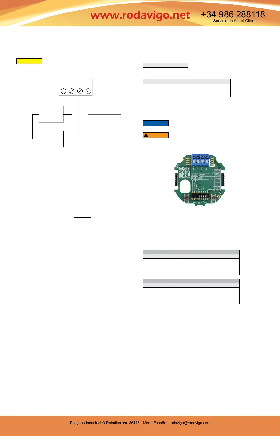
Figure 5 is a depiction of a 5 in w.c. pressure board. Other pressure
boards, while similar, will vary from the below.
NOTICE
There are no hazardous voltages if supplied power is within the
specied range. However, it is a good idea to shut control systems
down while changing DIP switches to prevent erratic control system behavior.
WARNING
Current Output
Supply Voltage 10-36 VDC
Loop Resistance 0-1250 Ω
Voltage Output
Supply Voltage 17-36 VDC
21.6 to 33 VAC isolated
Minimum Output Load Resistance 1000 Ω
PRESSURE UNIT SELECTION - DIP SWITCH 3 IS OFF (DOWN)
DIP Switch 1 DIP Switch 2 Unit of Measure
ON
ON
OFF
OFF
ON
OFF
ON
OFF
Pa (low ranges)
Pa (high ranges)
mm w.c.
in w.c.
VELOCITY/FLOW UNIT SELECTION - DIP SWITCH 3 IS ON (UP)
DIP Switch 1 DIP Switch 2 Unit of Measure
ON
ON
OFF
OFF
ON
OFF
ON
OFF
m
3
/hr (Flow)
m/s (Velocity)
CFM (Flow)
FPM (Velocity)
Figure 5: 5 in w.c. pressure board
RMAX =
(V
PS – 17.0)
20 mA DC
0
-
!A
!
Polígono Industrial O Rebullón s/n. 36416 - Mos - España - rodavigo@rodavigo.com
https://rodavigo.net/
Polígono Industrial O Rebullón s/n. 36416 - Mos - España - rodavigo@rodavigo.com
Servicio de Att. al Cliente
+34 986 288118
 Loading...