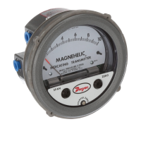
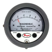
Series 605 Magnehelic
®
Differential Pressure Indicating Transmitter
Specications - Installation and Operating Instructions
Bulletin E-68
The Series 605 Magnehelic
®
Differential Pressure Indicating Transmitter
simultaneously provides local indication on a large, easily read analog scale while
also converting that pressure into a standard two-wire, 4-20 mA signal for ranges from
0-0.5 to 0-50 in w.c. Positive, negative or differential air and compatible gas pressure
can be measured with accuracies as low as ±.5% of full scale. The basic mechanical
components of the Series 605 Magnehelic
®
indicating transmitter are similar to those
used in the popular, time-proven Magnehelic
®
differential pressure gage.
STANDARD ACCESSORIES
Mounting ring
Snap ring
(4) 6-32 x 1-1/4 screws (panel mtg.)
(3) 6-32 x 5/16 screws (surface mtg.)
(2) Tubing to 1/8˝ NPT adapters
(2) 1/8˝ NPT plugs
Adjustment key
SPECIFICATIONS
Gage Specications
Service: Air and non-combustible, compatible gases.
Wetted Materials: Consult factory.
Accuracy: See chart.
Stability: ±1% FS/yr.
Pressure Limits: See chart.
Temperature Limits: 20 to 120°F (-6.67 to 48.9°C).
Process Connections: 1/8˝ female NPT.
Size: 4˝ (101.6 mm) dial face, 5˝ (127 mm) O.D. x 2-11/16˝ (68.3 mm); For -SS
Bezel: 4-3/4˝ (120.7 mm) O.D. x 2-21/32˝ (67.5mm).
Weight: 1 lb, 12.6 oz (811 g).
Agency Approvals: CE.
TRANSMITTER SPECIFICATIONS
Accuracy: See chart (includes linearity, hysteresis, repeatability).
Temperature Limits: 20 to 120°F (-6.67 to 48.9°C).
Compensated Temperature Range: 32 to 120°F (0 to 48.9°C).
Thermal Effect: ±0.025% FS/°F (0.045% FS/°C).
Power Requirements: 10-35 VDC (2-wire).
Output Signal: 4-20 mA.
Zero and Span Adjustments: Protected potentiometers.
Loop Resistance: DC; 0-1250 Ω maximum.
Current Consumption: DC; 38 mA maximum.
Electrical Connections: Screw terminal block.
Mounting Orientation: Diaphragm in vertical position. Consult factory for other
position orientations.
23/32
[18.26]
1
[25.40]
30°
1-1/8
[28.58]
(3) #6-32 x 3/16 [4.76]
HOLES EQUALLY SPACED
ON A Ø4-1/8 [104.78] B.C.
FOR PANEL MOUNTING
11/16
[17.46]
1/8 FEMALE NPT
LOW PRESSURE
CONNECTION
1/2 [12.70]
1-3/4
[44.45]
1/8 FEMALE
NPT HIGH
PRESSURE
CONNECTION
2-1/16
[52.39]
2
[50.80]
1-1/4
[31.75]
2-1/2
[63.50]
3/16
[4.76]
5/8 [15.88]
PANEL MAX
Ø5
[127.00]
Ø4-47/64
[ 120.25]
EQUALLY SPACED ON
A 5-1/8 [130.18] B.C.
FOR FLUSH MOUNTING
Ø4 [101.60]
FACE
5-1/2 [139.70]
O.D. MOUNTING
MODEL CHART
Model
Range
in w.c.
Maximum
Pressure
Electrical
Accuracy ±%
Mechanical
Accuracy ±%
605-00N
605-11
605-0
605-1
605-2
605-3
605-6
605-10
605-20
605-30
605-50
.05-0-.20
.25-0-.25
0-.50
0-1.0
0-2.0
0-3.0
0-6.0
0-10
0-20.0
0-30
0-50
10 psi (68.95 kPa)
10 psi (68.95 kPa)
10 psi (68.95 kPa)
10 psi (68.95 kPa)
2 psi (13.79 kPa)
2 psi (13.79 kPa)
2 psi (13.79 kPa)
2 psi (13.79 kPa)
11 psi (75.8 kPa)
11 psi (75.8 kPa)
11 psi (75.8 kPa)
4
2
2
2
0.5
0.5
0.5
0.5
0.5
0.5
0.5
4
3
3
2
2
2
2
2
2
2
2
Model
Range
in Pa
Maximum
Pressure
Electrical
Accuracy ±%
Mechanical
Accuracy ±%
605-12
605-13
605-60PA
605-125PA
605-250PA
605-500PA
60-0-60
100-0-100
0-60
0-125
0-250
0-500
10 psi (68.95 kPa)
10 psi (68.95 kPa)
10 psi (68.95 kPa)
10 psi (68.95 kPa)
10 psi (68.95 kPa)
2 psi (13.79 kPa)
4
2
2
2
2
0.5
4
2
4
3
2
2
DWYER INSTRUMENTS, INC.
P.O. BOX 373 • MICHIGAN CITY, INDIANA 46360, U.S.A.
Phone: 219/879-8000
Fax: 219/872-9057
www.dwyer-inst.com
e-mail: info@dwyermail.com