ELECTRICAL CONNECTIONS
CAUTION: DO NOT EXCEED SPECIFIED SUPPLY VOLTAGE RATINGS.
PERMANENT DAMAGE NOT COVERED BY WARRANTY WILL RESULT. THIS UNIT
IS NOT DESIGNED FOR AC VOLTAGE OPERATION.
Electrical connections to the Series 605 Transmitter are made to the two-screw
terminal strip on the rear of the case. Polarity is indicated by + and – signs stamped
on side. The schematic diagram of the Series 605 transmitter is illustrated in Figure B.
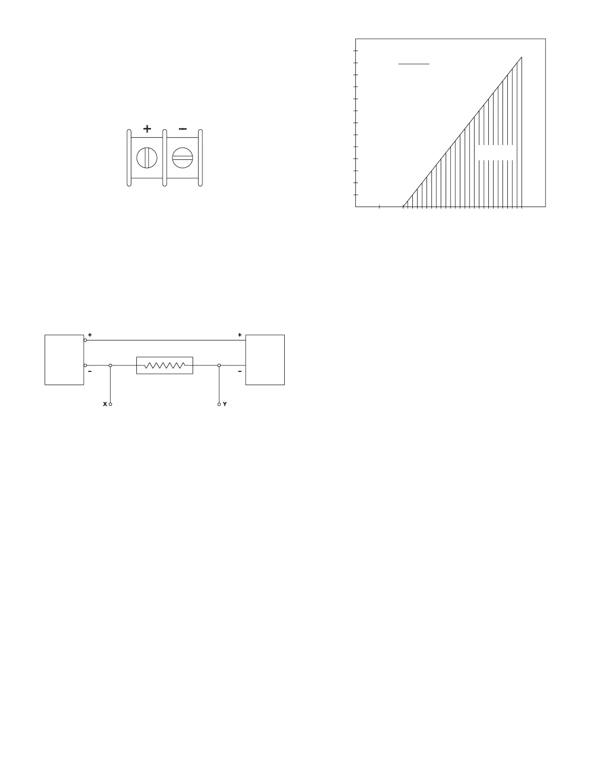
An external power supply delivering 10.0-35 VDC with a minimum current capability of
40 milliamps must be used to power the control loop in which the Series 605 transmitter
is connected. Refer to Figure B for connection of the power supply, transmitter and
receiver. The range of appropriate receiver load resistances (RL) for the power supply
voltage available is given by the formula and graph in Figure C. Shielded two wire
cable is recommended for control loop wiring and the negative side of the loop may
be grounded if desired. Note also that the receiver may be connected in either the
negative or positive side of the loop, whichever is most convenient. Should polarity of
the transmitter or receiver be inadvertently reversed, the loop will not function properly
but no damage will be done to the transmitter.
The maximum length of connecting wire between the transmitter and the receiver is
a function of wire size and receiver resistance. That portion of the total current loop
resistance represented by the resistance of the connecting wires themselves should
not exceed 10% of the receiver resistance. For extremely long runs (over 1,000 feet),
it is desirable to select receivers with higher resistances in order to keep the size and
cost of the connecting leads as low as possible. In installations where the connecting
run is no more than 100 feet, connecting lead wire as small as No. 22 Ga. can be used.
The Series 605 transmitters can be used with receivers requiring 1 to 5 V input rather
than 4-20 mA. If the receiver requires a 1-5 V input, insert a 250 Ω, 1/2 watt resistor in
series with the current loop but in parallel with the receiver input. Referring to Figure B,
RL becomes the 250 Ω resistor and point X and Y are connected to the receiver input,
point X being positive (+) and point Y negative (–) or ground. The resistor should be
connected at the panel end of the transmitter current loop close to the receiver input
to take advantage of the immunity of the current loop to electrical noise pickup. Most
electronic component distributors stock a 249 r, 1/2 watt, ±1% tolerance metal lm
resistor which is adequate for this application
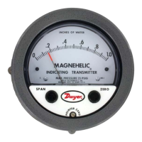
OUTPUT RANGING
Each Series 605 Magnehelic
®
indicating transmitter is factory calibrated to produce
4 mA at zero scale reading and 20 mA at full scale reading. The following procedure
should be used if the pressure versus output signal relationship needs to be checked.
1. With unit connected to the companion receiver per preceding instructions, insert
an accurate milliammeter with a full scale reading of approximately 30 mA in
series with the current loop.
2. Vent both pressure ports to atmosphere and, if necessary, adjust pointer zero
screw to align pointer with zero on scale. A controllable pressure source capable
of reaching the full scale range should be connected to either high pressure
port. Plug the other high pressure port and vent one or both low pressure ports
to atmosphere. The instrument must be ranged in the same position in which it
will be used. Standard factory calibration and ranging is done with unit vertical.
3. Apply electrical power to the system and check for proper operation by slowly
increasing pressure and observing whether the loop current increases above the
4 mA zero pressure reading.
4. A spanner type key is supplied to adjust span and zero. This helps to reduce
unauthorized tampering. Apply pressure until pointer aligns with full scale reading
and adjust the SPAN knob for a 20 mA reading.
5. Relieve all pressure, allow a few seconds for setting and adjust the ZERO knob
for a 4 mA current loop reading.
6. The SPAN and ZERO controls are slightly interactive so steps 4 & 5 should be
repeated a few times until readings of 4 and 20 mA are obtained consistently.
7. Remove the milliammeter from the current loop and proceed with nal installation
of the transmitter and receiver.
Figure B
Figure C
Figure A
1300
1200
1100
1000
900
800
700
600
500
400
300
200
100
0
51015 20
25
30 35
40
RECEIVER RESISTANCE RL (W)
POWER SUPPLY VOLTAGE - VDC
RL MAX = VPS - 10.0V
20 mA DC
MAXIMUM VALUE (1250)
OPERATING
REGION
SERIES 605
PRESSURE
R
POWER
SUPPLY
10.0-35 VDC
RECEIVER (RL)
SEE FIGURE C
SERIES WITH + OR -
LEG OF CONTROL LOOP
 Loading...