Printed in U.S.A. 4/19 FR# 443847-00 Rev. 8©Copyright 2019 Dwyer Instruments, Inc.
DWYER INSTRUMENTS, INC.
P.O. BOX 373 • MICHIGAN CITY, INDIANA 46360, U.S.A.
Phone: 219/879-8000
Fax: 219/872-9057
www.dwyer-inst.com
e-mail: info@dwyermail.com
Sensor Replacement
A replacement sensor is available from Dwyer Instruments.
For CO, order part number: A-505
For NO
2, order part number: A-506
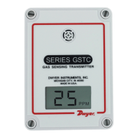
Replacing the Sensor
1. Remove the cover plugs from the face of the unit and top cover. Locate the
sensor, see Figure 3 – the sensor is mounted on three pin sockets. The circuit
board is labeled either “CO SENSOR” or “NO2 SENSOR” underneath the
sensor.
2. Remove and discard the sensor.
3. Remove the shorting wire spring located on the bottom of the new sensor.
4. Install the new sensor into the three pin sockets.
5. The unit must be re-calibrated whenever a new sensor is installed.
6. Allow 30 minutes for the unit to come to temperature equilibrium prior to
calibration. The unit has internal temperature compensation, and the sensor
must be at the same temperature as the unit to calibrate properly.
TROUBLESHOOTING
1. Verify that the unit is mounted in the correct position.
2. 4 to 20 mA Models: Verify appropriate supply voltage. The transmitter requires
a minimum of 10 and a maximum of 35 VDC at its connection for proper
operation. Choose a power supply with a voltage and current rating that meets
this requirement under all operating conditions. If the power supply is
unregulated, make sure voltage remains within these limits under all power line
conditions. Ripple on the supply should not exceed 100 mV.
Loop Resistance – The maximum allowable loop resistance depends on the power
supply voltage. Maximum loop voltage drop must not reduce the transmitter voltage
below the 10 VDC minimum. Maximum loop resistance can be calculated with the
following equation. Vps is the power supply voltage.
Rmax =
Some receivers, particularly loop powered indicators, may maintain a xed loop
voltage to power the device. This voltage drop must also be subtracted from the power
supply voltage when calculating the voltage margin for the transmitter. The following
equation takes this into account. Vrec is the receiver xed voltage.
Rmax =
0 to 10 V Output Models: Verify appropriate supply voltage. The 0 to 10 V output
models require a DC supply of 15 to 35 V or an AC supply of 15 to 29 V for proper
operation maximum. Maximum output load is 5 mA.
MAINTENANCE
Upon nal installation of the Series GSTA Transmitter and the companion receiver,
no routine maintenance is required with the exception of calibration. As with all
electrochemical type gas sensors, routine calibration is required. It is recommended
that units be re-calibrated at 6 month intervals, to maintain the published accuracy,
or as required by local ordinances or other requirements. The units will maintain 5%
accuracy if they are re-calibrated at 12 month intervals.
Except for sensor replacement and calibration, the Series GSTA is not eld serviceable
and should be returned if repair is needed (eld repair should not be attempted
and may void warranty). Be sure to include a brief description of the problem plus
any relevant application notes. Contact customer service to receive a return goods
authorization number before shipping.
V
ps
-10.0
20 mA
Vps
-10.0-V
rec
20 mA
Sensors contain acid. Do not attempt to open sensors. Sensors
should be disposed of according to local laws.
WARNING
 Loading...