OPERATING PRINCIPLE
Capacitance and Dielectrics
Capacitance is the property of two or more conductors to store a charge
when there is a voltage difference between the conductors. In other
words, capacitance relates the voltage between two conductors and the
amount of charge that can be held on the conductors (i.e., the number of
electrons). Capacitance is measured in Farads, but since a Farad of
capacitance represents a very large charge storage capacity, most
capacitance encountered is generally measured in micro Farads (µF, 10
-
6
) or pico Farads (pF, 10
-12
). Capacitances encountered in level sensing
applications are generally in the pico Farad range.
The material between the conductors also affects the capacitance.
Insulating materials do not allow free movement of electrons, however,
in an electric field the molecules of these materials will tend to align with
the field, thus storing energy. This is called the dielectric effect and these
materials are often referred to as dielectrics. When placed between two
conductors the energy storage capability of these dielectrics will allow
more charge to be stored on the conductors for a given voltage
difference thus increasing the capacitance between the conductors. The
ratio of capacitance change caused by these dielectrics is referred to as
the dielectric constant. Different materials have differing dielectric
constants and will consequently change the capacitance between two
conductors more or less depending on the value of this constant. This
value ranges from 1.0 for a vacuum to over 100 for certain materials. The
dielectric constant for air is very close to 1.0 and usually assumed to be
exactly 1.0.
Capacitive level sensors determine the level of material by changes in
probe capacitance resulting from the movement of dielectric materials
between the probe and the reference ground such as a tank wall. Since
measuring very small capacitance changes (less than 1 pF) can be
problematic in industrial environments, capacitance level sensing tends
to be most effective for materials with a dielectric constant greater than
about 1.2. Since the difference in capacitance is being measured, it is
also possible to detect the level of two immiscible liquids that have
different dielectric constants such as oil and water.
Level Detection
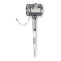
The CLS2 uses the capacitance difference between the uncovered
sensor and covered sensor to sense level such as the probe in air verses
the probe in oil. This would allow, for instance, detection when the level
in a tank is below a threshold and a pump must be started or when the
level is above a threshold where the pump must be turned off.
The CLS2 can be used in applications were the probe gets coated or
covered with sticky, dusty, or clingy materials. The CLS2 has an active
guard near the top that compensates for material that coats the probe
preventing false alarms.
When detecting level, two critical items must be established: a reference
capacitance and the sensitivity. The reference capacitance is set through
an automatic calibration process. The sensitivity is selected using an
internal DIP switch which provides 8 sensitivity levels to accommodate
differing material dielectric constants. See the calibration section for
specific calibration instructions.
The level detection is available to external systems through a double
pole double throw (2-form C) relay. In any alarm or control system some
consideration must be made for a power failure in one or more elements
of the system. The CLS2 provides a fail-safe selection that allows the
relay to operate in either a normally open or a normally closed state
when the probe is uncovered.
INSTALLATION
Unpacking
Remove the CLS2 from the shipping carton and inspect for damage. If
damage is found, notify the carrier immediately.
Example
Series
Enclosure
Switch
Power Supply
Probe Type
Insulator
Material
Process
Connection
Probe Length
Options
CLS
2
CLS
2
W
W
1
1
1
1
R
R
C
K
K
1
1
2
3
4
5
6
7
8
019
XXX
MC
MC
WC
FG
T
CLS2-W11RK1-019-MC
Capacitive Level Switch
Watertight/Corrosion Resistant
DPDT rated 8A @ 12/240 VAC, 30 VDC res.
12-240 VAC/DC
Standard Rod: 316 SS, .375˝ diameter
Cable: 316 SS with weight
Kynar
®
3/4˝ male NPT
1˝ male NPT
1-1/2˝ male NPT
3/4˝ BSPT
1˝ BSPT
1-1/2˝ BSPT
1-1/2˝ Sanitary Clamp
2˝ Sanitary Clamp
Insertion length in inches. Example 019 is 19˝ length.
(Minimum length is 6˝, with 3/4˝ sensing tip)
M20 conduit connection
Window Cap
Food Grade Wetted Materials
Rod: 316 SS, .375˝ diameter, with 3/8-16 threaded tip
MODEL CHART
L-26:Series QV (F-87) 6/1/10 2:19 PM Page 2


 To Next Page
 Loading...