Mounting Location
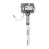
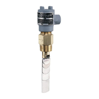
The CLS2 is designed to be mounted in a tank and is rated for industrial
environments with few restrictions, however certain considerations must
be made to ensure optimal sensing and extended operational life.
• The process temperature and ambient temperature must be within the
specified limits for the instrument.
• Avoid locating the unit near or in high mechanical shock or vibration
areas.
• The probe must be located away from tank inlets or chutes where
material may fall on the probe during filling or emptying.
• Avoid mounting the probe close to tank structures as conductive
product bridging between the guard and tank structure can cause false
alarms.
• In nonmetallic tanks a ground reference must generally be provided. If
the probe is near the wall of the tank an adhesive backed metallic sheet
may be applied to the outside of the tank wall nearest to the probe. Other
metallic objects may be used also if they are in close proximity to the tank
wall. If the probe is located further than 10 inches from the wall, an
internal conductor must be provided parallel to and within 10 inches of
the probe. These conductors must be connected to the case ground of
the sensor. An external ground clamp is provided for this if other
grounding is not available.
Wiring
WARNING: Always install or service this device with the
power off and where required install a disconnect lockout.
CAUTION: For power line connections use NEC Class 1 wiring rated
75°C. Use 12 to 20 AWG copper only for line and load connections.
Torque terminals to 5 in-lb. Strip the wires 0.25˝.
Note: Installation must be made in accordance with National Electric
Code and local codes and regulations. When fishing wire through the
conduit connection do not allow the wire to touch or press on
components on the boards. Damage to the circuitry may result.
The unit is to be wired to a switch or circuit breaker in close proximity to
the unit. The switch or circuit breaker shall be marked as the
disconnections device for the unit.
The CLS2 has a 1/2˝ female NPT conduit connection. The conduit
connection must be made such that condensation is not allowed to enter
the housing.
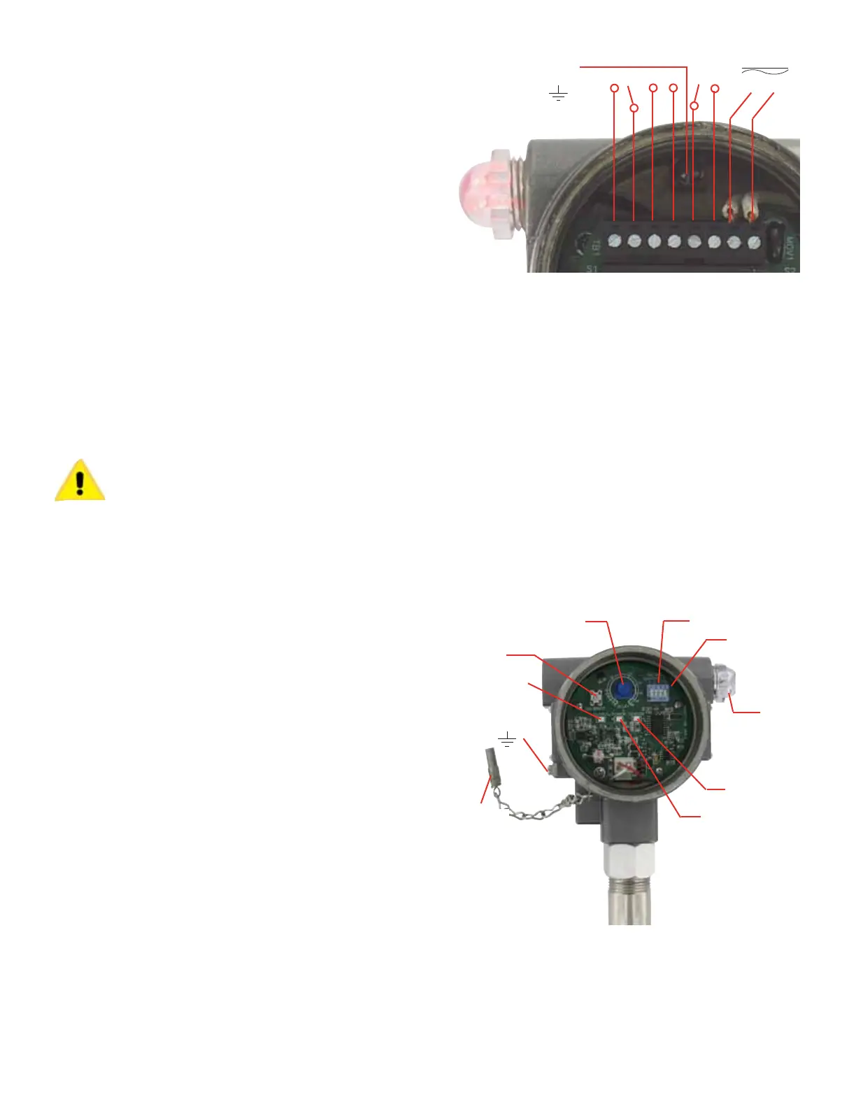
Grounding: The case of the CLS2 must be wired to a protective earth
ground. This may be done by using a metal conduit or by wiring to one
of the protective earth ground screws in Figure 1 or Figure 2.
The terminal block may be removed for easier connection. To remove,
place a small screwdriver between the terminal block and the connector
base and pry the terminal block forward. This will unlatch the block from
the base allowing it to be removed. When installing the block, tip it
forward on the connector base to snap it in the forward locking tab then
rock the connector back onto the contacts until it snaps in place. Make
sure the terminal block is securely in place.
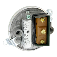
Strip 0.25˝ of insulation from the wires. Connect the power wires to
terminals 1 and 2. If powered by DC, the polarity is not critical and either
terminal may be selected for positive or negative. Connect control lines
to the relay contact terminals (see Figure 1 for terminals). Torque
terminals to 5 in-lb.
Controls and Indicators (See Figure 2 and 3)
Calibrate Switch—Pressing this switch twice initiates the automatic
calibration process.
Time Delay Potentiometer—This control selects a delay time from 0 to
60 seconds from the detection of a level change to the output.
Dip Switch—This four section switch selects the sensitivity level and
failsafe mode.
Sensor LED—Yellow. This LED is illuminated immediately when the
probe capacitance exceeds the setpoint threshold.
Output LED—Red. This LED is illuminated when the relay is powered.
It is affected by the failsafe setting and the delay.
Power LED—Green. This LED is illuminated when the unit is powered
and indicates that power is being supplied to the sensing circuitry.
External LED—Red. The external LED indicator operates in conjunction
with the internal Output LED.
External Calibration Magnet—An external magnet is provided on the
end of a chain to initiate calibration without having to open the case.
Calibration is started by touching the magnet to the label target twice.
NC
C
NO
NO C NC
L2 L1
Time Delay
Potentiometer
Calibrate
Switch
Output LED
(RED)
Power LED
(GREEN)
Sensor LED
(YELLOW)
External
LED
Failsafe
Sensitivity
External
Calibration
Magnet
Protective Earth
Ground Screw
Protective
Earth
Ground Screw
Figure 2: Switches and LED’s
Figure 1: Terminals
L-26:Series QV (F-87) 6/1/10 2:19 PM Page 3


 To Next Page
 Loading...