Do you have a question about the DYNATEK Dyna 4000 Super Pro DP4000-1S and is the answer not in the manual?
Choose a mounting place for the DYNA 4000 away from ignition coils and spark plug wires.
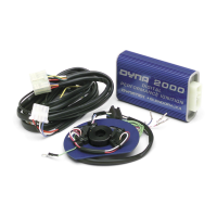
Plug the large 21-position harness connector into the 4000 SP ignition module.
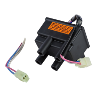
Mount the DC9-2 Twinfire coil close to spark plugs and connect plug wires.
Route the three-wire leg of the main harness to the ignition coil, away from other wiring.
Connect the black three-position plug housing to the Twinfire coil, mating wire colors.
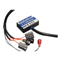
Connect the four-wire leg of the main harness (crank trigger group) to the Crank Trigger plug.
Connect the four-wire leg (red/white, purple/white) to a normally-open clutch switch.
Connect the orange and black wires to either side of a normally open air kill switch.
Connect the black and red 12-gauge power wires directly to the battery terminals.
Ensure the special blue two-magnet rotor is installed for proper system operation.
Static time the motor by watching the red LED as the second magnet nears the sensor.
Check +12V to coil and ignition enable wire; verify crank trigger rotor orientation.
Adjust the left knob for low launch limit and the right knob for high over rev limit.
Rev limiter settings are read only when the unit is first turned on.
| Model | Dyna 4000 Super Pro |
|---|---|
| Part Number | DP4000-1S |
| Voltage Range | 9-16 VDC |
| Current Consumption | 0.5A |
| Rev Limit | Adjustable |
| Timing Adjustment | Programmable |