then the adjustment screw must be turned -87.6 degrees
(negative = ccw rotation as viewed from the rear of the
instrument) or about ccw 1/4 of a full turn to bring it back
into calibration per ASTM requirements. Use a 1/8" Allen
Wrench to turn the adjustment screw.
5. Recheck the encoder calibration by repeating the
micrometer measurements in steps 2 & 3. If further
adjustment is required then again use Table 1 to determine
the appropriate degrees of movement. Repeat this process
until the arm is calibrated. Once the arm is calibrated,
secure the arm in place by re tightening the second arm set
screw (see Figure 1). Apply removable thread locker
(Loctite
type 290 or equivalent). Reinstall the cover and
tighten all hardware.
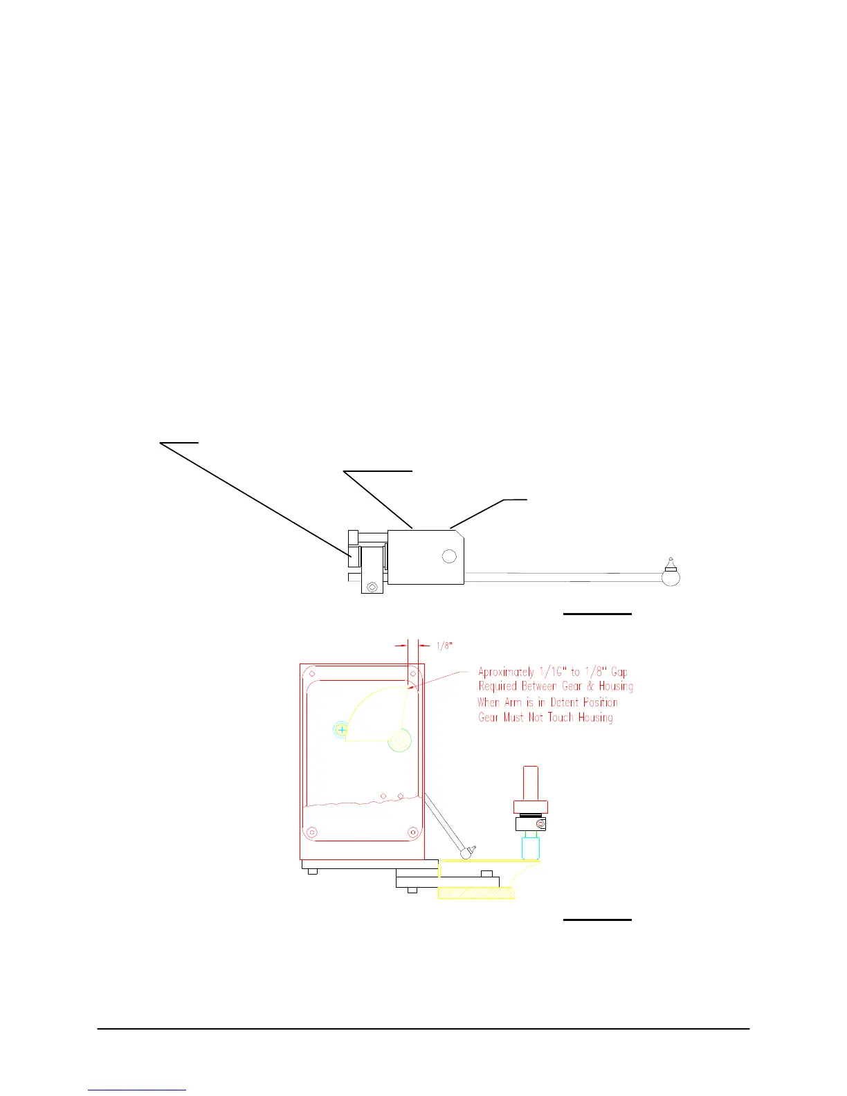
ADJUSTMENT SCREW: TURN CW TO EXTEND ARM
TURN CCW TO RETRACT ARM
SECOND SET SCREW LOCKS ARM IN PLACE
LOOSEN THIS SET SCREW TO CALIBRATE ENCODER
FIRST SET SCREW SECURES
ARM TO SHAFT
DO NOT LOOSEN THIS SET SCREW!
Figure 1
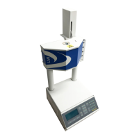
Figure 2
Series 4000 Melt Indexer Operation Manual The Digital Encoder: Use and Calibration
56