2-39
DYNO INSTALLATION
Tire Carriage Installation
Version 4 Above Ground Model 250i Motorcycle Dynamometer Installation Guide
1 Replace the center panel using the six 1/4-inch screws you removed.
See Figure 2-2 on page 2-3.
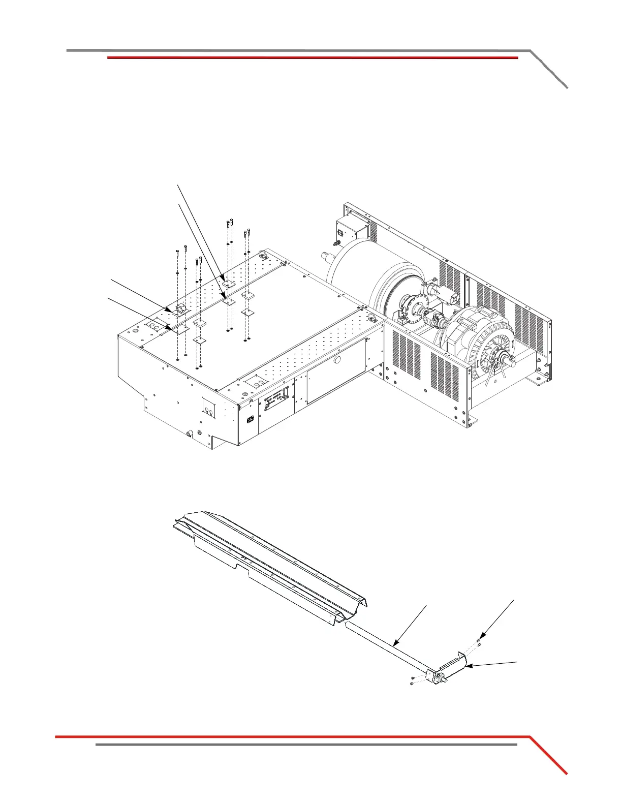
2 Install the three carriage clamps and spacers using two 5/16-inch bolts and
washers each.
3 Install the nut block and spacer using two 5/16-inch bolts and washers.
Figure 2-34: Install the Carriage Clamps and Nut Block
4 Remove the four 1/4 x 20-inch button-head screws securing the bearing bracket.
5 Remove the bearing bracket and the carriage screw.
Figure 2-35: Remove the Bearing Bracket and Carriage Screw
carriage clamp
spacer
nut block
spacer
screw
bearing
bracket
carriage
screw