2-41
DYNO INSTALLATION
Tire Carriage Installation
Version 4 Above Ground Model 250i Motorcycle Dynamometer Installation Guide
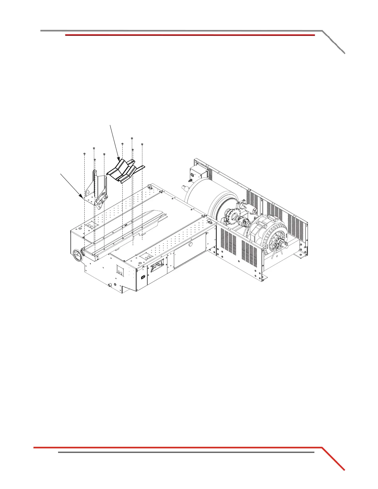
12 Secure the tire stop to the carriage using four 3/8-16 x 1/2-inch button-head
flange bolts.
Note: If you purchased the wheel clamp accessory, refer to “Wheel Clamp” on
page 3-39 for installation instructions.
13 Secure the tire lock to the carriage using four 3/8-16 x 1/2-inch button-head
flange bolts.
Figure 2-37: Install the Tire Stop and Tire Lock


 To Next Page