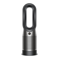
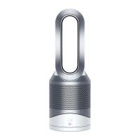
103 Run the left handside of the Base
Skirt anti-clockwise aroun the base.
Clip the securing tab in the base.
104 Run the right handside of the Base Skirt clockwise aroun the base.
Clip the securing tab in the base.
105 Fit the Two T-8 screws.
58
After fitting the harness, continuing fitting the following components as previously shown:
Lower boby assembly (pages 31 - 35, steps 46 - 55)
Air AMP Service assembly (Pages 21 - 24, steps 25 - 30)
Parts diagram
Main body
59
Pump column PCB assy
Motor & Bucket
Service Assy
Motor Bucket Seal
Tail Cone
Evaporator Assy
Pump Column
Assy
Water Tank Assy
Citric Acid
Pump Column
Base Cap
Tank Handle
Service Assy
Lower Body Assy
Tray Level Sensor Assy
Clean Cycle PCB Assy
LCD Display Service Assy
Internal Input Harness
Service Assy
Humidifier Controller
PCB Assy
Evaporator
Access Door
Pump Column Lid
Connection Shuttle
Service Assy
Shuttle Spring
Foot Pad
Service Assy
Base Skirt
Service Assy
Power Supply Unit
 Loading...
