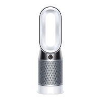
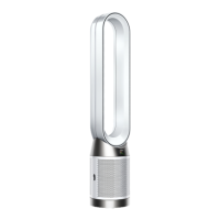
06 At this point any of the PCB’s can be replaced
Note: the Dust sensor and Dust sensors PCB are within the AMP Service assembly.
For removal instructions of these parts continue to the next step.
Note: not all PCBs are available as spare parts at launch. Always check Dyson Central for
availability.
12
Main PCB
LCD assembly
Deep clean
cycle PCB
Humidifier PCB
Wifi PCB
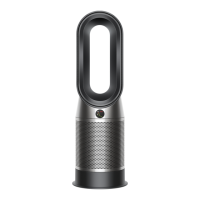
07 Remove the two T-8 screws holding the
dust sensor and sensors PCB service
assembly into the base of the amp.
Carefully unclip the Dust sensor to
main controller loom. Remove the
Dust sensor and Sensors PCB service
assembly.
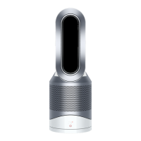
08 To remove the Power button, lever out the two arms and push out the Button, spring and Foam.
To replace the Air Amp Neck Service assembly go to the next step.
For Amp service assembly fitting instructions go page17 step16.
For Lower body service assembly - removal go to page 25 step 31.
For Motor and Bucket service assembly - removal go to page 36 step 56.
If the reason for the repair is to replace the Air amp neck service assembly or the On/Off button service
assembly, continue to the next step.
13