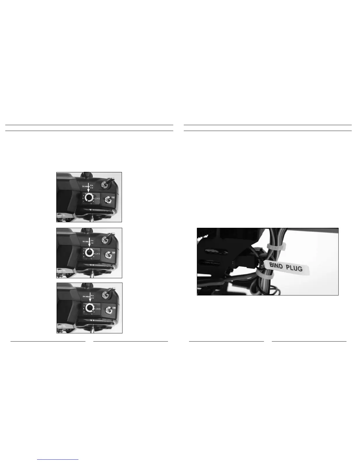
Channel5Knob
TheHP6DSMtransmitterisequippedwithanoptional-usechannel5knob(CH5)locatedontheforwardtoprightpanel,
next to the dual rate switch.
This knob allows you to control function of the transmitter’s fifth channel. And while this channel remains unused for
flying the Blade SR, it is available for use in controlling a variety of potential optional features including actuation of
a servo, electronic components or even for setting the gain of a gyro remotely from the transmitter. It allows fully
proportionalcontrolofthefifthchannelfromapproximately0–100%travel.
Though servo reversing is available for this channel, the knob can be operated in either direction for control. You can
use either the most clockwise (+) or most counterclockwise (-) position for 0 or 100% travel, and you will achieve
approximately 50% travel with the knob in the middle position, pointing directly to the rear of the transmitter.
0% (or 100%) Travel
50% Travel
100% (or 0%) Travel
Transmitter, Receiver Binding and Fail-Safe
BindingistheprocessofprogrammingthereceivertorecognizetheGUID(GloballyUniqueIdentifier)codeofasingle
specifictransmitter.Ifyoueverhavetoreplacethetransmitterorthereceiverforyourmodel,youwillneedto“bind”
the new transmitter or receiver to your existing transmitter or receiver for proper operation.
During the binding process, the smart fail-safe (SmartSafe™) positions of your system are also set. With SmartSafe, in
case of loss of signal, the throttle will go to the preset position that was stored during the binding process and all other
channels will hold their last position. And if the 2-in-1 control unit and receiver are powered on before the transmitter,
all channels but throttle will go to the fail-safe positions that were stored during the binding process, while the throttle
channel will not generate a pulse in order to prevent the ESCs from arming.
Note: Because the SmartSafe positions are set during the binding process, it is important to set all
channels to the preferred fail-safe positions before proceeding. In the case of the Blade SR,
we strongly recommend setting the throttle stick and throttle trim to their lowest positions, and
the rudder, aileron and elevator sticks and trims to their neutral positions. Channel 5 should
be set to your preferred position if you have chosen to use it.
The following steps outline the binding process:
Note: For added safety, disconnect both the main and tail motors from the 2-in-1 control unit before
proceeding. Once the binding process is complete and the flight battery is unplugged from the
2-in-1 unit, reconnect the main and tail motor to the 2-in-1 unit.
• InordertobindtheSpektrumAR6100ereceivertothetransmitter,youmustfirstconnecttheincludedbind
plug to the battery (BATT) channel pins on the receiver. Then you will need to power on the 2-in-1 unit and
receiver by connecting the flight battery to the 2-in-1 BEFORE powering the transmitter on.
• Whenyouconnecttheflightbatterytothe2-in-1unitwiththebindplugconnectedtothebatterychannelpins
on the receiver, you will see an orange LED blink rapidly on the receiver itself.


 To Next Page