Remember,
there must be some movement
between the boat and
the
fish
to
develop
the arch.
Usually
this
means
trolling
at
very
slow
speeds
with the
main
engine
in
gear
at
a minimum throttle
setting.
The
depth
of the water will affect
the size and
shape
of the fish arch
due to the
cone
angle
diameter. For
example,
if
the cone
passes
over
a
fish in
shallow
water,
the
signal displayed
on the Z-5000
may
not arch at
all,
due to
the narrow cone diameter
and the resolution limitations of the
display.
Even
the 20
degree
transducer has
only
a 3 foot diameter at
this
depth.
Compared
to a
paper graph,
an Z-5000 cannot
show as fine of detail
because the
pixels (dots
on the
screen)
are much
larger
than a
paper
graph's
markings.
Therefore,
the Z-5000 cannot show
fish arches as well
as a
graph,
and
it
requires
a bit more work
initially
to read and
interpret
the screen than
a
paper graph.
Very
small fish
probably
will not arch at
all,
while medium
sized fish will
show a
partial
arch,
or a
shape
similar to an arch if
they're
in
deep
water
Large
fish will
arch,
but
the
sensitivity
needs to be
turned
up
in
deeper
water to see
the arch. Because of water
conditions,
such
as
heavy
surface
clutter, thermoclines,
etc.,
the
sensitivity
sometimes
cannot be
turned
high enough
to
get
fish arches.
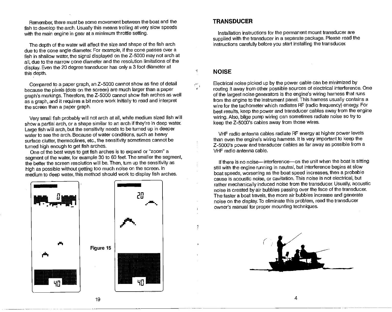
One of the best
ways
to
get
fish arches is to
expand
or "zoom"
a
segment
of the
water,
for
example
30 to 60 feet The smaller
the
segment,
the better the screen resolution
will be.
Then,
turn
up
the
sensitivity
as
high
as
possible
without
getting
too much noise on the screen.
In
medium to
deep
water,
this method
should work to
display
fish arches.
TRANSDUCER
Installation instructions
for the
permanent
mount transducer
are
supplied
with the transducer
in a
separate package.
Please
read the
instructions
carefully
before
you
start
installing
the transducer.
NOISE
Electrical
noise
picked up by
the
power
cable can be minimized
by
routing
it
away
from other
possible
sources of electrical interference.
One
of the
largest
noise
generators
is the
engine's wiring
harness
that runs
from the
engine
to the instrument
panel.
This harness
usually
contains a
wire for
the tachometer which
radiates RF
(radio frequency) energy.
For
best results,
keep
the
power
and
transducer cables
away
from the
engine
wiring. Also, bilge pump wiring
can
sometimes radiate noise so
try
to
keep
the Z-5000's cables
away
from
those wires.
VHF
radio antenna cables
radiate RF
energy
at
higher power
levels
than even the
engine's
wiring
harness.
It is
very important
to
keep
the
Z-5000's
power
and transducer
cables as far
away
as
possible
from
a
VHF
radio antenna cable.
If there
is no noise—interference—on
the unit when the boat is
sifting
•
still
with the
engine running
in
neutral,
but interference
begins
at slow
boat
speeds, worsening
as the
boat
speed
increases,
then a
probable
cause
is acoustic
noise,
or cavitation.
This noise is not
electrical,
but
•
rather
mechanically
induced
noise from the transducer.
Usually,
acoustic
noise
is created
by
air bubbles
passing
over the face of the transducer.
The faster a boat
travels,
the more
air bubbles increase and
generate
noise
on the
display.
To eliminate
this
problem,
read the transducer
owner's
manual for
proper
mounting techniques.
U
______
In
[LI
a
I.'
Ilk'
Figure
15
I
-
_rJ
19
4
PDF compression, OCR, web-optimization with CVISION's PdfCompressor