EasyManua.ls Logo

Eastwood ARC 80 20295 User Manual

Eastwood ARC 80 20295
8 pages
To Next Page IconTo Next Page
Page #1 background imageLoading...
Page #1 background image
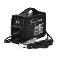
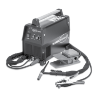
ARC 80 WELDER
ASSEMBLY & OPERATING INSTRUCTIONS
Item #20295

Questions and Answers:

Eastwood ARC 80 20295 Specifications

General IconGeneral
BrandEastwood
ModelARC 80 20295
CategoryWelding System
LanguageEnglish

Summary

Statement of Limited Warranty

Warranty Period

Provides details on warranty duration for products.

Conditions of Warranty to Obtain Warranty Coverage

Outlines requirements for obtaining warranty service from Eastwood.

Warranty Repair

Explains the process and options for warranty repair or replacement.

Freight Costs

Specifies responsibility for shipping costs related to warranty claims.

Warranty Limitations

Details exclusions and limitations of the provided warranty coverage.

Specifications

Safety Information

Read Instructions!

Emphasizes the importance of reading the manual before operation.

Electric Shock Can Kill!

Details critical precautions to prevent electric shock hazards.

Fumes and Welding Gases Can Be Dangerous!

Warns about dangers of welding fumes and recommends ventilation.

Welding Sparks Can Cause Fire or Explosion!

Advises on fire prevention and safe operation around flammable materials.

Safety Information

Arc Rays Can Burn!

Warns about arc ray hazards and protective measures for eyes and skin.

Hot Metal Will Burn!

Highlights burn risks from hot metal and necessary precautions.

Electromagnetic Fields May Be Dangerous!

Discusses potential interference of EM fields with medical devices.

Flying Metal Chips Can Cause Injury!

Warns about flying metal chips and the need for eye protection.

Magnetic Fields Can Affect Pacemakers!

Advises pacemaker users to consult a doctor before welding.

Notice!

Provides a critical safety notice regarding electrical contact.

Duty Cycle

Includes

Components & Controls

Power Switch

Describes the location and function of the main power switch.

Power Indicator LED

Explains the function of the power indicator light.

Thermal Protection LED

Details the thermal protection indicator and its meaning.

Amperage Adjustment Knob

Explains how to adjust the welding amperage.

"Stick"/TIG Switch

Describes the switch for selecting welding modes.

Positive (+) Connector

Identifies the positive connector for cable attachment.

Negative (-) Connector

Identifies the negative connector for cable attachment.

Welder Set-Up for Arc or "Stick" Welding

"Stick" Welding

Provides step-by-step instructions for performing stick welding.

Troubleshooting

Accessories

Related product manuals