

R
Rachel ThomasAug 1, 2025
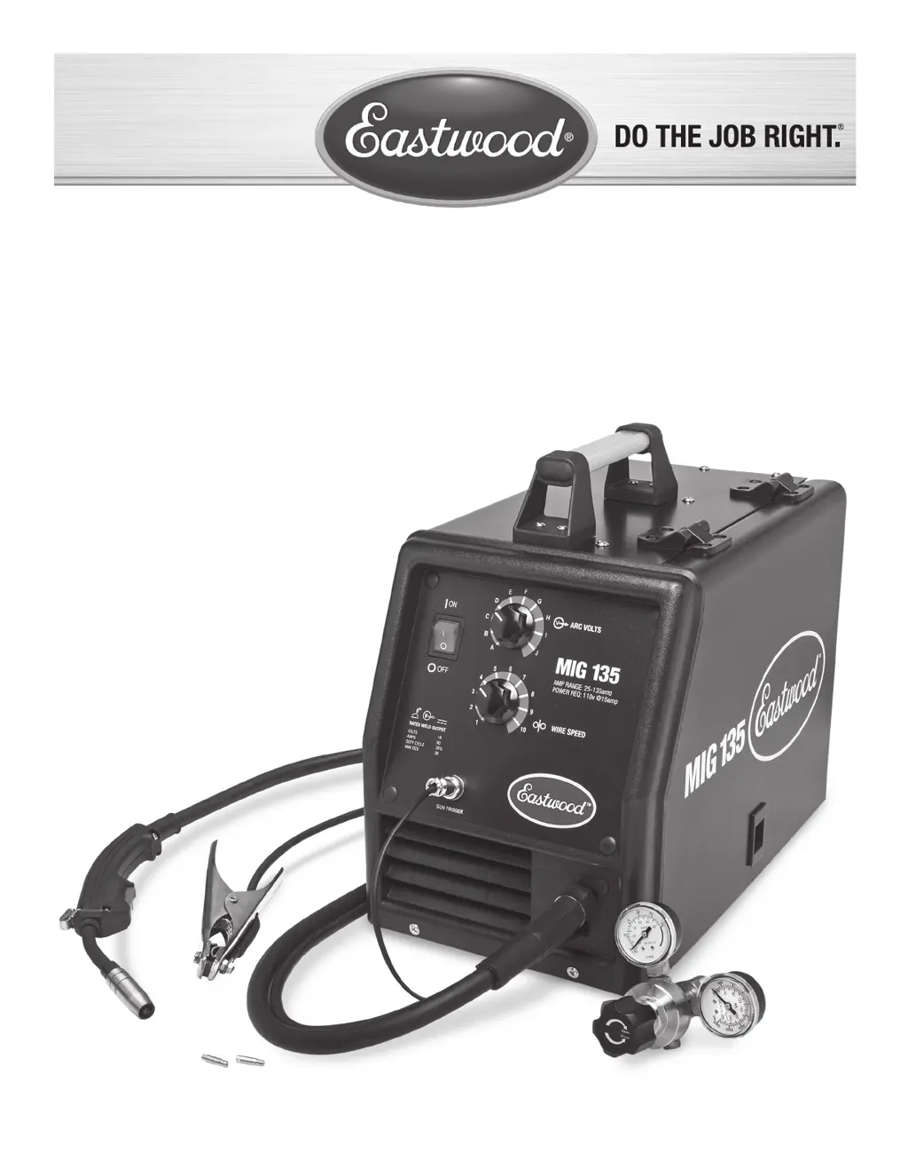
Why is there excessive spatter when using my Eastwood Mig135 Welding System?
- AAllison MartinezAug 1, 2025
Excessive spatter can occur due to several factors. You might have the wire speed set too fast; try adjusting it to a slower setting. Ensure the base metal is clean by removing any paint, rust, oil, grease, dirt, or contaminants from the surface. Check that you're using the correct shielding gas (75% Argon / 25% CO2) and increase the flow rate, being mindful of any crosswinds. Verify that the welding wire is appropriate for the material and process. Also, make sure the contact tip on the welding gun is closer to the workpiece to shorten the exposed welding wire.