Instruction Book
Effective: November 2017 Page 25
IB131016EN For more information visit: www.Eaton.com
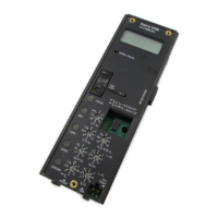
Figure 4-4 Position Circuit Breaker With Lifter On
Removable Extension Rails
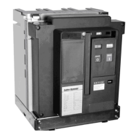
Figure 4-5 Breaker Shoot Locked into Cassette
NOTICE
A number of labels have been applied to the
circuit breaker and its cassette to facilitate the
connection and disconnection of the secondary
umbilical cord, inserting the circuit breaker,
levering the circuit breaker to the CONNECT
position and removal of the circuit breaker. These
operations are also described in detail in this
instruction book. Become familiar with the labels
as they not only provide assistance initially, but
provide a good quick reference at a later date when
the instruction book may not be readily available.
With secondary connections to the circuit breaker
only made as supplied from the factory, carefully
position the circuit breaker directly in front of its
cassette using appropriate slings and an overhead
lifter as described earlier in paragraphs 3-2.2 and 3-
2.3 (Figure 4-4). The cradle portion (bottom portion) of
the drawout circuit breaker is provided with integrally
mounted wheels for rolling on the removable
extension rails and the floor of the cassette in a guided
manner.
Position the circuit breaker so that the two rear wheels
begin to roll on the cassette’s floor and then firmly
push the circuit breaker into the cassette until the
horizontal shoot bolts on either side of the breaker
cradle contact the front of the cassette (Figure 4-5).
Care should be taken not to bind the secondary
umbilical cord between the circuit breaker and
cassette as the circuit breaker is pushed into its
cassette. At this point the breaker cannot be inserted
any further until the shoot bolts are retracted using the
spring loaded shoot bolt handle on the lower left side
of the cradle (Figure 4-6). The lifting slings can now be
removed from the circuit breaker.
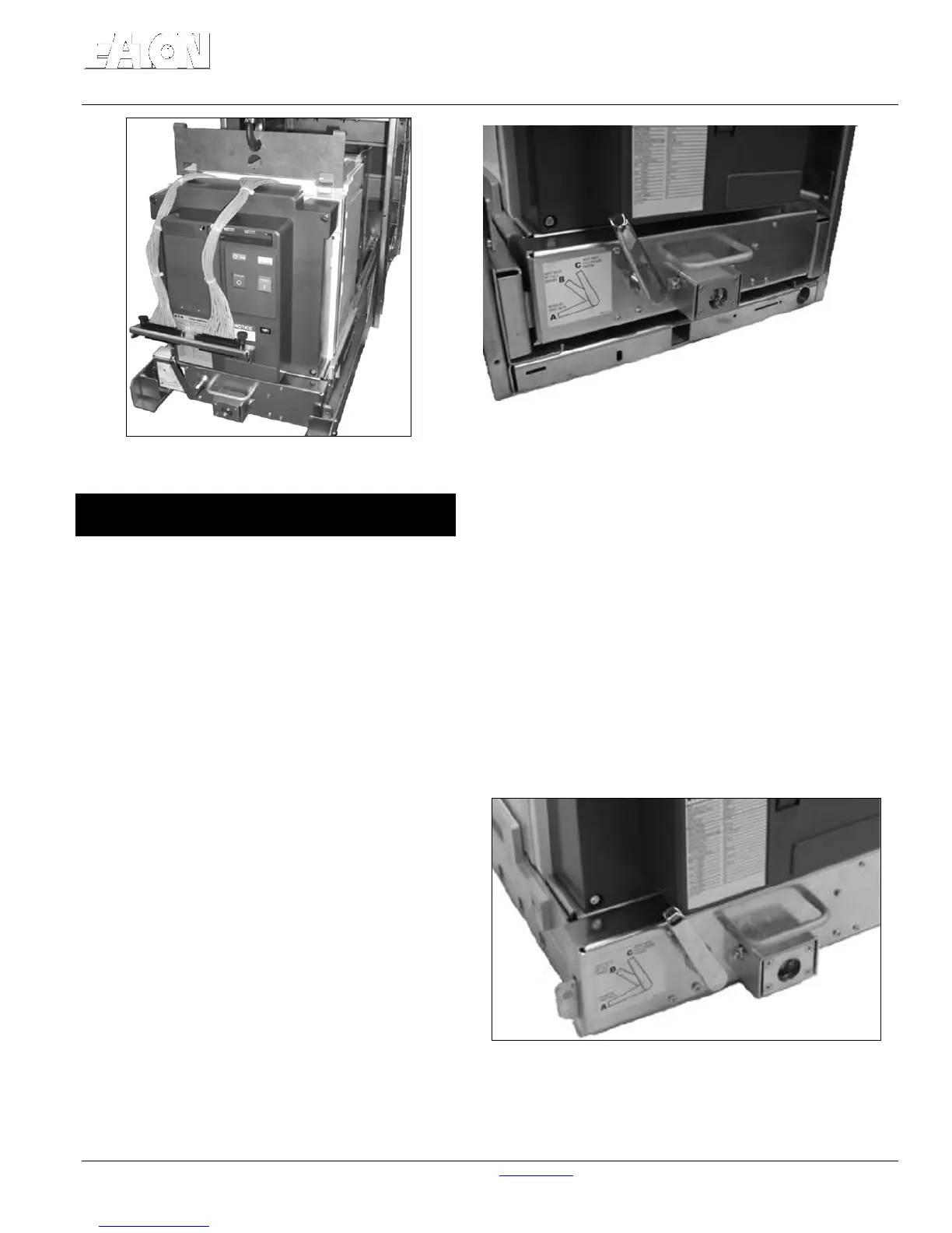
The shoot bolt handle as shown in Figure 4-6 has
three labeled positions
Position “A” - Full down position causing the shoot
bolts to retract fully inside the breaker cradle (not
engaged)
Position “B” - Partially up position causing the shoot
bolts to only protrude partially (partially engaged).
Position “C” - Full up position which causes the shoot
bolts to protrude completely (fully engaged).
These three handle positions are important and play a
critical role while connecting and disconnecting the
secondary umbilical cord to and from the drawout
cassette as well as during insertion and removal of the
circuit breaker from the cassette.
Figure 4-6 Shoot Bolt Handle in Up (Locked) Position
 Loading...