Do you have a question about the Eaton 520 and is the answer not in the manual?
Basic components of circuit breaker overload fault detection by Digitrip units.
Current sensors providing signals to the Digitrip unit for overload protection.
The mechanism that converts electrical energy into mechanical tripping force.
Guide to understanding trip unit catalog numbers and their protection features.
Overview of protection features available for Digitrip trip units.
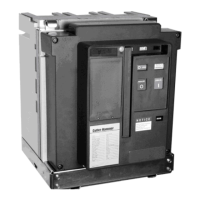
Steps for installing the Digitrip trip unit into the Series NRX circuit breaker frame.
Procedure for inserting and securing the rating plug into the trip unit.
Instructions for safely removing the trip unit and its rating plug.
Details on internal and external wiring connections for the trip unit.
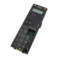
Description of the clear, tamper-proof cover for viewing settings.
Requirements for auxiliary voltage and alarm functions.
How the ground fault alarm operates and is indicated.
Information on ground fault trip contacts and reset procedures.
Explains how trip units operate using microcomputers and digitized signals from sensors.
Details the meaning of trip unit LEDs for status and trip cause indication.
Describes the safety feature preventing closing on a faulted circuit.
Explains the high instantaneous trip feature for NF and RF frames.
How zone interlocking provides selective tripping for faults within protected zones.
Explains the use of trip unit LEDs for diagnosing circuit breaker or trip unit problems.
General considerations for applying ground fault protection.
Covers Residual, Source Ground, and Zero Sequence sensing modes for ground fault protection.
Guidelines for setting trip unit protection parameters based on installation requirements.
Details on setting long delay pickup (I₁) and time delay (t₁) for overload protection.
Instructions for setting short delay pickup (I sd) and time delay (t sd) for selective coordination.
How to set the instantaneous trip pickup (I₁) for fast fault clearing.
Configuration of ground fault pickup (I) and time delay (t) for ground fault protection.
Safety precautions and general instructions before performing tests.
Recommended timing and conditions for testing trip units.
Procedures for performing field tests on trip units using approved kits.
Description and use of the handheld test kit for trip unit functionality.
Detailed steps for conducting tests, including current settings and battery checks.
Information on performance testing for ground fault trip units.
Explains the battery's role in maintaining trip indication, not protection.
How to check the battery status using the Battery Check button and LED.
Step-by-step guide for replacing the trip unit's battery safely.
How the rating plug defines the rated current (In) and bases trip unit settings.
Details on the groupings and catalog numbers for NF frame rating plugs.
Explains the function of Maintenance Mode in reducing arc flash incident energy during faults.
Details the fixed pickup current values used when Maintenance Mode is armed.
Describes the methods (local, remote, communication) to arm the Maintenance Mode.
How to remotely indicate that Maintenance Mode is actuated via a contact.
How Maintenance Mode affects tripping and how to verify its functionality.
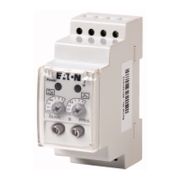
Introduces communication modules for Digitrip 520M and supported networks.
Lists relevant Eaton documentation for Series NRX circuit breakers and components.
Lists available time-current curves for NF and RF frame models.
Information about the "CurveSelect" software tool for visualizing tripping characteristics.
Demonstrates standard time delay coordination without zone interlocking.
Shows how zone selective interlocking provides faster fault clearing.
Lists common symptoms like LED status, unexpected tripping, and battery issues with probable causes.
Addresses issues like breaker tripping too rapidly, LED flashing, and cause of trip LEDs retriggering.
Detailed table of trip pickup, trip time, and tolerances for protection functions.
Includes frequency, temperature, metering accuracy, and control voltage consumption.
Specifications for alarm relay contacts under AC and DC loads.
Requirements for ground fault protection system testing in North America.
Minimum instructions required by UL Standard No. 1053 for ground fault systems.
General guidelines for personnel conducting tests on interconnected systems.
Instructions for using forms to record test data and initial trip function settings.
Detailed master connection diagram for Series NRX-NF frame breakers.
Explanations and notes related to the NF frame breaker connection diagrams.
Detailed master connection diagram for Series NRX-RF frame breakers.
Explanations and notes related to the RF frame breaker connection diagrams.
| Voltage | 120 V |
|---|---|
| Input Voltage | 120 V |
| Input Frequency | 50/60 Hz |
| Output Voltage | 120 V |
| Output Frequency | 50/60 Hz |
| Warranty | 2 years |
| Operating Temperature | 0° to 40°C (32° to 104°F) |