Effective 8/13/99
Page 1I.L. 70C1037H02
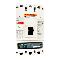
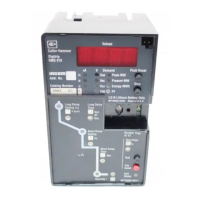
Instructions for Digitrip Models 220, 520, 520i, 520M, and
520Mi Trip Units for use only in Cutler-Hammer Magnum
and Magnum DS Circuit Breakers
Table of Contents
1.0 General Description of Digitrip Trip Units................ 2
1.1 Protection ............................................................... 4
1.2 Mode of Trip and Status Information....................... 4
1.3 Installation and Removal ........................................ 4
1.3.1 Installation of the Trip Unit ........................... 4
1.3.2 Rating Plug Installation................................ 4
1.3.3 Trip Unit/Rating Plug Removal .................... 5
1.4 Wiring ..................................................................... 6
1.5 Plexiglass Cover..................................................... 6
1.6 Ground Alarm/Power Supply Module
(520M Models only) ................................................ 6
1.6.1 Auxiliary Power............................................ 6
1.6.2 Ground Alarm.............................................. 6
1.7 Display Feature (520M family only)......................... 7
1.8 Standards ............................................................... 7
2.0 General Description of
Magnum Circuit Breakers ....................................... 7
2.1 General .................................................................. 7
2.2 Low Energy Trip Actuator ....................................... 8
2.3 Ground Fault Protection ......................................... 8
2.3.1 General ....................................................... 9
2.3.2 Residual Sensing ........................................ 9
2.3.3 Source Ground Sensing .............................. 9
2.3.4 Zero Sequence Sensing .............................. 9
2.3.5 Multiple Source/Multiple Ground.................. 9
2.3.6 Ground Fault Settings ................................. 9
2.4 Current Sensors (Magnum Frames less than
or equal to 3200A) ................................................ 10
2.5 Current Sensors (Magnum Frames greater
than 3200A) .......................................................... 10
3.0 Principles of Operation ......................................... 10
3.1 General ................................................................ 10
3.2 Trip and Operation Indicators ............................... 15
3.3 Making Current Release ....................................... 15
3.4 Zone Interlocking (520 family only) ....................... 15
4.0 Protection Settings ............................................... 19
4.1 General ................................................................ 19
4.2 Long Delay Current Setting................................... 19
4.3 Long Delay Time Setting ...................................... 19
4.4 Short Delay Current Setting .................................. 20
4.5 Short Delay Time Setting ...................................... 20
4.6 Instantaneous Current Setting .............................. 20
4.7 Ground Fault Current Setting................................ 21
4.8 Ground Fault Time Delay Setting.......................... 21
5.0 Test Procedures ................................................... 21
5.1 General ................................................................ 21
5.2 When to Test ........................................................ 22
5.3 Functional Field Testing ........................................ 22
5.4 Performance Testing for Ground Fault
Trip Units .............................................................. 22
5.4.1 Code Requirements .................................. 22
5.4.2 Standards Requirements........................... 22
5.4.3 General Test Instructions........................... 22
6.0 Battery ................................................................. 23
6.1 General ................................................................ 23
6.2 Battery Check ....................................................... 23
6.3 Battery Installation and Removal .......................... 24
7.0 Frame Ratings
(Sensor Ratings and Rating Plugs)................ 10, 24
8.0 Record Keeping.................................................... 25
9.0 References ........................................................... 25
9.1 Magnum and Magnum DS Circuit Breakers ......... 25
9.2 Time-Current Curves ............................................ 25
Appendix A Zone Interlocking Examples ...................... 29
Appendix B Troubleshooting Guide .............................. 31
Appendix C Typical Breaker Master
Connection Diagram ............................................. 33
WARNING
DO NOT ATTEMPT TO INSTALL OR PERFORM
MAINTENANCE ON EQUIPMENT WHILE IT IS
ENERGIZED. DEATH OR SEVERE PERSONAL INJURY
CAN RESULT FROM CONTACT WITH ENERGIZED
EQUIPMENT. ALWAYS VERIFY THAT NO VOLTAGE IS
PRESENT BEFORE PROCEEDING. ALWAYS FOLLOW
SAFETY PROCEDURES. CUTLER-HAMMER IS NOT
LIABLE FOR THE MISAPPLICA-TION OR
MISINSTALLATION OF ITS PRODUCTS.
WARNING
OBSERVE ALL RECOMMENDATIONS, NOTES,
CAUTIONS, AND WARNINGS RELATING TO THE
SAFETY OF PERSONNEL AND EQUIPMENT. OB-
SERVE AND COMPLY WITH ALL GENERAL AND
LOCAL HEALTH AND SAFETY LAWS, CODES, AND
PROCEDURES.
I.L. 70C1037H02
Courtesy of NationalSwitchgear.com