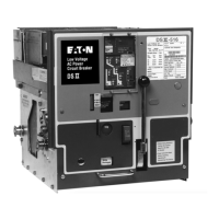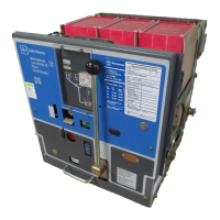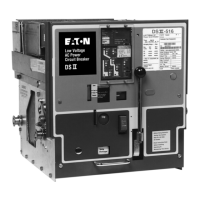
Do you have a question about the Eaton Cutler-Hammer DSII Series and is the answer not in the manual?
| Number of Poles | 1, 2, 3 |
|---|---|
| Trip Type | Thermal-Magnetic |
| Frame Type | DSII |
| Voltage | 240V, 480V, 600V |
| Type | Circuit Breaker |
| Standards | UL Listed, CSA Certified |
| Series | DSII Series |
Provides general information on Type DSII and DSLII low voltage power circuit breakers.
Highlights built-in safety features designed to reduce operational hazards.
Details essential safety practices for personnel working with circuit breakers.
Defines the qualifications required for personnel operating or maintaining breakers.
Lists additional resources and documentation for circuit breaker information.
General information regarding the receiving and handling of switchgear assemblies.
Procedure for safely unpacking a circuit breaker unit.
Guidelines for proper storage of circuit breakers before installation.
Instructions for safely lifting and positioning circuit breakers.
Visual inspection procedures to check for damage after removal from packaging.
Details on operating the circuit breaker levering mechanism for position changes.
Explanation of the function and use of drawout dummy elements.
Description of the fixed type DSII circuit breaker variant.
Overview of the design and features of Type DSII circuit breakers.
Description of the Type DSLII breaker with integral current limiters.
Details on the main components of the basic circuit breaker assembly.
Description of the pole unit assemblies in DSII circuit breakers.
Technical description of the primary moving contact assembly.
Technical description of the primary stationary contact assembly.
Function and importance of interphase barriers for safety.
Details on the DE-ION arc chute assembly and its function.
Overview of the circuit breaker's electronic tripping system.
Detailed explanation of the electronic trip unit's features and functions.
Description of the current sensors within the tripping system.
Explanation of the trip actuator's role in the tripping system.
Description of the spring-charged stored energy operating mechanism.
Details on the manually operated circuit breaker mechanism.
Details on the power operated circuit breaker mechanism.
Description of movable primary and secondary disconnecting contacts.
Overview of standard and optional devices available for circuit breakers.
Function of the Motor Cut-Off Switch (LS).
Operation of the Spring Release Device (SRD).
Functionality of the Anti-Pump Relay (Y).
Operation of the Shunt Trip Attachment (STA).
Function of the Latch Check Switch.
Specifications and types of Auxiliary Switches.
Operation of the Undervoltage Trip Attachment (UVTA).
Function of the Overcurrent Trip Switch.
Details on various miscellaneous components and features.
Functionality and purpose of the interference interlock.
Purpose and function of the ground contact.
Description and function of the close bar guard.
Details on the breaker operation counter.
Step-by-step instructions for manual operation of circuit breakers.
Details on the spring charging mechanism for manual operation.
Overview of the operation for power operated circuit breakers.
Details on the spring charging mechanism for power operation.
Explains the electrical power operation sequence for circuit breakers.
Description of the breaker's closing mechanism principles.
Explanation of the breaker's opening and tripping mechanisms.
Detailed description of the mechanical interlocking system.
Interlocking conditions in the REMOVE position.
Interlocking conditions in the DISCONNECT position.
Interlocking conditions in the TEST position.
Interlocking conditions in the CONNECT position.
How the mechanical interlocking system operates.
Function of the spring discharge interlock.
Manual close interlock for connected breakers.
Electric lockout feature for preventing unauthorized closing.
Interlock preventing closing when breaker is already closed.
Mechanism for padlocking the breaker in a trip-free condition.
Information on DSLII circuit breakers and associated fuse trucks.
Specifications and application of DSLII current limiters.
Function of the blown limiter indicator.
Description of the DSII fuse truck.
Guidelines for installing and using DSII fuse trucks.
Procedure for replacing fuses in DSII fuse trucks.
Function of the blown fuse indicator on fuse trucks.
General guidelines for inspection and maintenance of circuit breakers.
Recommended procedures for cleaning circuit breaker components.
Guidance on the recommended timing and frequency for inspections.
Checklist of components and areas to inspect on circuit breakers.
Specific inspection points for DSII-308 to DSII-620 models.
Specific inspection points for DSII-632, DSII-840/850 models.
Procedure for replacing stationary contacts on DSII-308 breakers.
Procedure for replacing contacts on DSII-516 to DSII-840/850 models.
Inspection and potential replacement of arc chutes.
Inspection of the power operated mechanism components.
Overview of factory set adjustments and when they apply.
Procedure for adjusting the trip latch overlap.
Adjustment procedure for open position stop on DSII-632.
Procedure for adjusting the moving contact engagement.
Procedure for adjusting the levering mechanism.
General guidelines and requirements for circuit breaker lubrication.
Recommended intervals for circuit breaker lubrication.
Identification of lubrication points on the breaker mechanism.
Information on obtaining renewal parts and ordering procedures.


