Page
20
Potential
Power Relay Module
Transformer
-----
Module
Terminal
__
__
Block
Shutter
Trip Plate
Spring Charge Indicator
Digitrip Trip Unit
Hold Pawl
l.B.
694C694-02
Emergency
Charge Handle
Spring Charge
Motor
Opening Spring
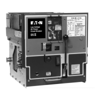
Figure 3-16 Power Operated OSI/ Breaker (Front Cover Removed)
3-10.5 LATCH CHECK SWITCH
The latch check switch consists of a switch mounted
on
the inside of the left hand breaker side sheet. It is locat-
ed such that when the breaker trip shaft is
in
the "reset"
position, a normally closed contact of the switch is
closed (Figure
3-17). When the switch is supplied, the
contact is usually connected
in
the closing circuit of the
breaker to insure that the tripping system is reset before
the circuit can be energized to close the breaker.
3-10.6 AUXILIARY SWITCH
Up to two auxiliary switches can be mounted on a
breaker (Figure 3-16). They are stacked units located
in
the right front portion of the breaker chassis. Each
switch has nine contacts which may be normally open
"a"
or
normally closed "b" contacts. Auxiliary switch con-
tacts are rated 1 O amperes at 120/240 volts AC, 1 O
amperes at 125 volts DC, and 2 amperes at 250 volts
DC. Two normally open and two normally closed con-
tacts
or
five normally open and five normally closed con-
tacts are available for use
on
both manually and power
operated breakers.
3-10.7 UNDERVOLTAGE TRIP ATTACHMENT
(UVTA)
The undervoltage trip attachment is optional
on
both
manually
or
power operated breakers. The undervoltage
trip attachment is an electromechanical device that trips
the breaker when the voltage on its coil falls to between
30 to 60 percent of normal. The standard unit trips
instantaneously. A similar device is also available with a
non-adjustable time delay, intended to ride through
momentary fluctuations of system voltage.
In
operation, a moving core is normally held magnetical-
ly against a stationary core and a spring. This is linked
to a latch carrying a roller which restrains the main trip-
ping lever of this assembly (Figure 3-18). When the coil
voltage is sufficiently reduced, a spring overcomes the
magnetic attraction between the two cores. The moving
core travels upward, and rotates the latch counterclock-
wise so the roller moves from beneath the tail of the
main tripping lever. A torsion spring around the pivot pin
of the tripping lever then rotates it counterclockwise,
causing a projection on right side of this lever to strike a
pin
in
the mechanism trip shaft. The result is that the trip
shaft rotates clockwise and trips the breaker.
Effective
07
/97
Courtesy of NationalSwitchgear.com

 Loading...


