I.
B.
694C694-02
Compartment
Trip Lever
Interference
Interlock
Figure 3-14 Type OSI/ Circuit Breaker (Bottom View)
The secondary connection of a drawout circuit breaker
is provided by contact blocks mounted
on
the rear upper
frame of the circuit breaker. They are mounted, as
required,
in
two rows of two blocks per row. Each block
consists of 12 spring loaded contacts. Protective covers
over the top row of contacts help to protect from dam-
age (Figures
3-1
and 3-2).
3-10 STANDARD AND OPTIONAL DEVICES
3-10.1 MOTOR CUT-OFF SWITCH (LS}
The motor cut-off switch is standard on all power operat-
ed breakers. It disconnects the motor when the closing
springs are fully charged, and is operated by the motor
cut-off switch lever on the operating mechanism (Figure
3-14).
3-10.2 SPRING RELEASE DEVICE (SRO}
The spring release device is standard
on
power operat-
ed breakers and optional on manually operated break-
ers. It permits a breaker to be closed electrically. A
close signal is applied to the spring release device to
begin the closing operation. The spring release coil is
energized through the anti-pump relay, the motor cut-off
Effective
07
/97
Page
19
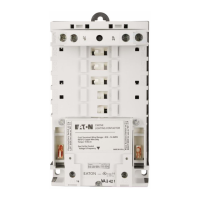
Figure 3-15 Anti-Pump Relay Shown Unmounted
switch, and a normally closed "b" auxiliary switch con-
tact, which operates the spring release latch to release
the closing springs.
3-10.3 ANTI-PUMP RELAY M
Power operated breakers have an anti-pump relay
mounted
in
the upper left front portion of the breaker just
behind the faceplate. It disconnects the spring release
device after the breaker has been closed (Figure 3-15).
This prevents the breaker from trying to close immedi-
ately after being tripped open (pumping) on concurrent
close and trip signals.
3-10.4 SHUNT TRIP ATTACHMENT {STA}
The shunt trip attachment is standard on power operat-
ed breakers and optional on manually operated break-
ers (Figure 3-16). It is an electromechanical device of
the clapper type. A trip signal to the shunt trip device
energizes a coil which causes its armature to be attract-
ed to the core. The armature pushes the trip lever on
the breaker trip shaft, causing the breaker to trip. As the
breaker trips, a normally open "a" auxiliary switch con-
tact
in
series with the shunt trip attachment coil de-ener-
gizes the coil.
Courtesy of NationalSwitchgear.com

 Loading...


