Effective 10/2004
Page 1I.L. 70C1036H05 I.L. 70C1036H05
Table of Contents
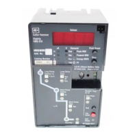
1.0 General Description of Digitrip Trip Units ................. 7
1.1 Protection ............................................................... 7
1.2 Mode of Trip and Status Information ........................ 7
1.3 Installation and Removal.......................................... 7
1.3.1 Installation of the Trip Unit ............................ 7
1.3.2 Rating Plug Installation ................................. 8
1.3.3 Trip Unit/Rating Plug Removal....................... 9
1.4 Wiring ..................................................................... 9
1.5 Plexiglass Cover ..................................................... 9
1.6 DT 1150 Power/Relay Module.................................. 9
1.6.1 Auxiliary Power............................................. 9
1.6.2 Alarm Contacts............................................. 9
1.7 Standards.............................................................. 10
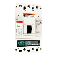
2.0 Description of Magnum Circuit Breakers ............... 10
2.1 General ................................................................. 10
2.2 Low-Energy Trip Actuator ...................................... 11
2.3 Ground Fault Protection ........................................ 11
2.3.1 General....................................................... 11
2.3.2 Residual Sensing (3 Wire or 4 Wire) ........... 12
2.3.3 Source Ground Sensing .............................. 12
2.3.4 Zero Sequence Sensing .............................. 12
2.3.5 Multiple Source/Multiple Ground ................. 12
2.3.6 Ground Fault Settings................................. 12
2.4 Current Sensors for Standard Breaker .................. 13
2.5 Current Sensors for Double Wide Breaker ............ 13
3.0 Principles of Operation .......................................... 13
3.1 General ................................................................. 13
3.2 Trip and Operation Indicators................................. 13
3.2.1 Status/Long Pickup LED............................. 13
3.2.2 Alarm LED .................................................. 14
3.2.3 Trip LED ..................................................... 14
3.3 Making Current Release ........................................ 14
3.4 Zone Interlocking ................................................... 14
3.5 PT Module ............................................................ 14
4.0 Programming/Viewing Digitrip 1150 ....................... 19
4.1 Main Menu ............................................................ 19
4.1.1 Power Up Sequence ................................... 19
4.1.2 Pushbutton Definition.................................. 19
4.1.3 Blink Mode ................................................. 22
4.1.4 Programming/Viewing Screens ................... 22
4.1.5 Reset Pushbutton Operation (After Trip) ..... 22
4.2 Program Settings PGM SET ................................. 22
4.2.1 CURRENT Curve Type Selection and
Pickup/Time Settings ................................. 22
4.2.2 VOLTAGE - Frequency, Reverse Power .... 26
4.2.3 INCOM Communications .......................... 28
4.2.4 Aux RELAYS .............................................. 28
4.2.5 ALARMS .................................................... 28
4.2.6 Digital Relay Accessory Module ................. 28
4.2.7 TripLink....................................................... 30
4.2.8 Setting TIME............................................... 31
4.2.9 Selecting DISPLAYS .................................. 31
4.2.10 SYSTEM Settings ...................................... 31
4.3 View Settings (VIEW SET).................................... 31
4.3.1 Firmware Menu ........................................... 31
4.4 METER Menu ....................................................... 31
4.5 HARMONIC Menu ................................................. 32
4.6 EventLOG ............................................................. 32
4.7 Power and Energy Parameters .............................. 32
4.8 Power Quality ....................................................... 33
4.8.1 Power Factor, THD and Crest Factor .......... 33
4.8.2 Alarms........................................................ 33
4.9 WAVEFORM CAPTURE Feature .......................... 33
4.9.1 Six Cycle Waveform Capture on Trip........... 33
4.9.2 One Cycle Waveform Capture ..................... 33
4.10 HEALTH ................................................................ 33
5.0 Test Procedures .................................................... 34
5.1 General ................................................................. 34
5.2 When to Test ........................................................ 34
5.2.1 Self Testing................................................. 34
5.2.2 Functional Field Testing .............................. 35
5.3 Performance Testing for Ground Fault Trip Units.... 35
5.3.1 Code Requirements .................................... 35
5.3.2 Standard Requirements .............................. 36
5.3.3 General Test Instructions ............................ 36
6.0 Battery .................................................................. 37
6.1 General ................................................................. 37
6.2 Battery Test .......................................................... 37
6.3 Battery Installation and Removal ........................... 37
7.0 Frame Ratings
(Sensor Ratings and Rating Plugs)........................ 38
8.0 Record Keeping .................................................... 38
9.0 References ............................................................ 39
9.1 Magnum and Magnum DS Circuit Breakers........... 39
9.2 Time-Current Curves .............................................. 39
Appendix A Zone Interlocking Examples....................... 43
Appendix B Troubleshooting Guide ............................... 45
Appendix C Typical Breaker Master
Connection Diagram .............................................. 47
Appendix D Display Menu Diagrams............................. 48
Appendix E Display Abbreviations ................................. 76
Appendix F Digitrip Settings and Descriptions.............. 78
Appendix G Auxiliary Relays ........................................ 81
Appendix H Digital Relay Accessory Module ................ 82
Appendix I Modbus Translator Wiring ........................ 83
Instructions for Digitrip Models 1150, 1150i and 1150
+
,
1150
+
i Trip Units for use only in Cutler-Hammer Magnum
and Magnum DS Circuit Breakers
Courtesy of NationalSwitchgear.com