Do you have a question about the Eaton Digitrip 520 and is the answer not in the manual?
Describes the protective functions offered by Digitrip trip units.
Explains how trip modes and unit status are indicated via LEDs.
Procedures for installing and removing Digitrip trip units and rating plugs.
Details on the optional module for 520M/MC units and communication enablement.
Information on internal breaker wiring and trip unit connection diagrams.
Description of the protective plexiglass door and its tamper-proof features.
How auxiliary power enables the LCD display and metering functions.
Functionality and indication of ground fault alarms in the trip unit.
Details on the high load alarm function for specific 520M/520MC models.
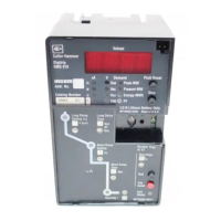
User interface and metering capabilities of 520M/520MC trip units.
Information on UL, CSA, and CE certifications for Digitrip units.
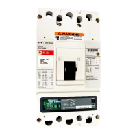
Visual examples of various Digitrip trip unit models and their settings.
Overview of Magnum circuit breaker components and the tripping mechanism.
Introduction to ground fault sensing methods and system considerations.
Explanation of the source ground fault sensing method and its application.
Details on the zero sequence sensing method for ground fault detection.
Description of the multiple source/multiple ground fault sensing scheme.
Information on adjusting ground fault current and time delay settings.
Overview of Digitrip trip unit design, internal operation, and power sources.
Explanation of LEDs and indicators for trip unit status and cause of trip events.
Safety feature preventing closure on faults by tripping instantaneously.
Explanation of the zone selective interlocking function for coordination.
Detailed explanation of the zone interlocking function and its operational logic.
General considerations for setting protection parameters on trip units.
Details on setting the long delay current pickup value based on frame rating.
Explanation of how to set the long delay time response based on current multiples.
Details on setting the short delay current pickup value based on long delay settings.
Explanation of how to set the short delay time response, FLAT or I²t.
Details on setting the instantaneous trip level, including M1 and OFF options.
Details on setting the ground fault current pickup values.
Explanation of how to set the ground fault time delay response, FLAT or I²t.
Information on INCOM communication setup, addressing, and network configuration.
General guidelines and warnings for performing tests on Digitrip trip units.
Recommendations on when and how to perform trip unit testing for proper operation.
Procedures for functional testing of trip unit operations using a test kit.
Description and operation of the battery-powered handheld test kit.
Information on the batteries used in the test kit and their maintenance.
Overview of the trip unit battery's purpose, function, and limitations.
Steps for safely replacing the trip unit's 3V lithium battery.
How to check the battery status using the Battery Check pushbutton.
Relationship between breaker frame ratings, sensors, and rating plugs for coordination.
Guidance on using forms for tracking trip function settings and test results.
List of documents, standards, and resources related to Digitrip and Magnum breakers.
Introduction to the Maintenance Mode function for arc flash energy reduction.
Details on the specific settings (R1-R5) for configuring the Maintenance Mode.
Methods for activating the Maintenance Mode function locally or remotely.
Example of standard time delay coordination without zone interlocking.
Example of how zone selective interlocking affects fault clearing time.
Common symptoms, probable causes, and solutions for Digitrip unit issues.
Diagram illustrating the master connection of breakers and Digitrip trip units.
Wiring details for using mMINT as a Modbus translator for Digitrip 520MC units.
Legal information regarding warranties and limitations of Eaton's liability.
| Category | Circuit Breakers |
|---|---|
| Trip Settings | Adjustable |
| Communication Protocol | Modbus RTU |
| Frame Type | Molded Case |
| Functions | Protection, Monitoring, Communication |
| Protection Features | Short Circuit |
| Standards | UL, CSA, IEC (Consult specific breaker documentation) |