22
Instructional Leaflet IL70C1037H05
Effective October 2009
Digitrip models 520, 520i; and 520M, 520Mi,
520MC, 520MCi trip units for use only in
Magnum and Magnum DS circuit breakers
EATON CORPORATION www.eaton.com
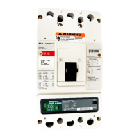
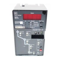
Figure 28. Digitrip 520MC ARMLSIA
Figure 29. Digitrip 520MC ARMWLSIG
Section 4: Protection settings
General
Before placing any circuit breaker in operation, set each trip
unit protection setting to the values specified by the engineer
responsible for the installation. The number of settings that must be
made is determined by the type of protection supplied by each unit,
as illustrated in Figure 16 through Figure 27. Each setting is made
by turning a rotary switch, using a small screwdriver. The selected
setting for each adjustment appears on the trip unit label.
The installed rating plug must match the current sensors that
establish the maximum continuous current rating of the circuit
breaker (I
n
). Instantaneous and ground current settings are defined
in multiples of (I
n
).
To illustrate the effect of each protection curve setting, simulated
time-current curves are pictured on the face of the trip unit. Each
rotary switch is located nearest the portion of the simulated time-
current curve that it controls. Should an automatic trip occur (as a
result of the current exceeding the pre-selected value), the LED in
the appropriate segment of the simulated time-current curve will
light red, indicating the reason for the trip.
The available settings, along with the effects of changing the
settings, are given in Figure 30 through Figure 37. Sample settings
are represented in boxes
2
.
Long delay current setting
There are eight available long delay settings, as illustrated in Figure
30. Each setting, called (I
r
), is expressed as a multiple (ranging from
0.4–1) of the current (I
n
). The nominal current pickup value is 110%
of the setting.
ote:N (I
r
) is also the basis for the short delay current setting (see page 23).
Figure 30. Long Delay Current Settings
Long Delay Setting l
r
1 x l
n
= l
r
l
r
Available Settings
0.4, 0.5, 0.6, 0.7,
0.8, 0.9, 0.95, 1.0
In Multiples of
Amperes (l
n
)
l
r

 Loading...