37
Instructional Leaflet IL70C1037H05
Effective October 2009
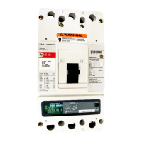
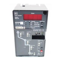
Digitrip models 520, 520i; and 520M, 520Mi,
520MC, 520MCi trip units for use only in
Magnum and Magnum DS circuit breakers
EATON CORPORATION www.eaton.com
Appendix C: Typical breaker master connection diagram
Figure 50. Typical Breaker Master Connection Diagram
WHT BRN
WHT BRN
BRNWHT
BLACK WHITE BROWN
B-28
B-29PDAD WIRES
B-24
B-25
52a
52b
AUX. SWITCH
(OPTIONAL)
B-26
B-27
B-21
B-20
B-22
B-23
10:1
ACTN
R/1 CSC
CSBR/1
R/1 CSA
1
ACTC
10:1
10:1
ACTB
1
1
ACTA
10:1
(OPT.)
(OPT.)
SEE NOTE 3
OST2_COM
OST1_COM
A-6
A-5
A-4
OTS2_MAKE
OST2_BREAK
OTS2
OTS1
SR
SR
AC
AC
SEE NOTE 2
BLACK
+
SEE NOTE 1#22 AWG
GF_SGND
ZONE_OUT
ZONE_IN
ZONE_COM
52b
LOAD
LINE
N
J2-6
J2-5
J2-4
J2-3
J2-2
J2-1
SUPPLIED)
J1-1
J1-2
J1-3
N
C
LL
BA
L
AC
AC
B-4
B-5
NEUTRAL2
NEUTRAL1
R/1
B-6
B-9
B-7
B-8
COIL C
HIGH INST.
HIGH INST.
COIL B
COIL A
HIGH INST.
24 OHM
(WHEN
MODULE
TRIP
INST.
HIGH
TA
K1-8
A2
K1-9
A1
K1-6
B2
K1-7
B1
K1-4
C2
K1-5
C1
K1-3
ST-
K1-2
ST1
K1-1
DGND
520/520M/520MC
DIGITRIP
PLUG
RATING
CLOSE CONTACT
CLOSE COILB-13
SR
B-12
OST1_BREAK
OST1_MAKE
A-1
A-2
A-3
B-10
A-8
UVR
A-7
A-15
A-14
A-11
A-10
GROUND ALARMPOWER SUPPLYMODULE520M / 520MC Only
J3-3
J3-2
J3-1
J4-2
J4-1
J4-4
J4-3
ATR V_COM
ATR_VOLT
ATR_ALARM
ATR_REL_COM
N2
N1
GF_SGND
G_ALARM
Z_OUT
Z_IN
+30VDC INPUT (520M ONLY)
Z_COM
BRKCLSD
K2-8
K2-9
K2-7
K2-6
K2-5
K2-4
K2-3
K2-2
K2-1
A-30
A-29
A-27
A-28
B-19
B-18
(OPTIONAL)
AUX. SWITCH
52b
52a
B-17
B-16
A-22
A-21
A-19
A-20
A-26
A-25
(OPTIONAL)
AUX. SWITCH
52b
52a
A-24
A-23
ST
AC
AC
B-11
UVR
UVR
ST
ST
B-30
G_ALARM
OUTPUT-
OUTPUT+
G_ALM 2
(MCR)
52a
SEE NOTE 5
G_ALM 1
2 1
H2
X2
X1
(OPT.)
(WHEN REQ.)
BRIDGE RECTIFIER
RESISTOR
(WHEN REQ.)
DOOR SWITCH
LEV-IN
SWITCH
MOTOR CUT-OFF
(WHEN REQ.)
A-16
MOTOR+
MOTOR-
ELECTRIC OPERATOR
MOTOR
AC
AC
SC
B-15
B-14
B2
INCOM 1
INCOM 2
B1
I1-1
I1-2
Notes:
1. Four-wire crimp connection.
2. Three-wire crimp if High Instantaneous Trip Module is supplied.
3. Three-wire socket used with Digitrip 520M Ground Alarm Power Supply Module will
“hang unconnected” if Digitrip 520 is supplied.
4. All auxiliary switches shown with breaker in open position and with spring not
charged and with trip unit in “non-tripped” state (OTS switches).
5. The “SR” device has additional circuitry that provides a 0.5 second signal pulse
for closing operation. Power must be removed and then reapplied for a subsequent
operation.
6. To provide selected time delays for short time and/or ground time functions for
testing or non-zone interlocking applications, a jumper from B-8 to B-9 is required.
7. On three-pole breakers only, having ground fault functionality, a jumper installed
from B-6 to B-7 will enable source ground fault sensing and disable residual ground
fault sensing inputs B-4 and B-5 will be reassigned for source ground sensor inputs.
For Digitrip 520MC Only

 Loading...