3
Instructional Leaflet IL70C1037H05
Effective October 2009
Digitrip models 520, 520i; and 520M, 520Mi,
520MC, 520MCi trip units for use only in
Magnum and Magnum DS circuit breakers
EATON CORPORATION www.eaton.com
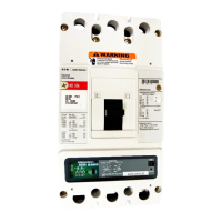
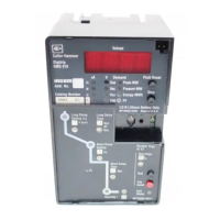
Figure 1. Digitrip 520MC Trip Unit with Rating Plug . . . . . . . . . . . . 5
Figure 2. Installation of the Digitrip Unit into a Magnum Breaker
(Side View). . . . . . . . . . . . . . . . . . . . . . . . . . . . . . . . . . . . . . . . . . . . 8
Figure 3. Installation of the Rating Plug and Mounting Screw . . . . 9
Figure 4. Ground Alarm/Power Supply Module for the
520M or 520MC Trip Units . . . . . . . . . . . . . . . . . . . . . . . . . . . . . . . 9
Figure 5. Wiring Diagram for 520M and 520MC Models
with Ground Alarm/Power Supply Module . . . . . . . . . . . . . . . . . . 10
Figure 6. Tripping Circuit for a Typical Magnum
Breaker (Partial) . . . . . . . . . . . . . . . . . . . . . . . . . . . . . . . . . . . . . . . 11
Figure 7. Three-Pole, Four-Wire Breaker with
Neutral Sensor Connections for 3200A Frame
Using Residual Ground Fault Sensing . . . . . . . . . . . . . . . . . . . . . . 13
Figure 8. Neutral Sensor Connections for 4000A Frame
Using Residual Ground Fault Sensing . . . . . . . . . . . . . . . . . . . . . . 13
Figure 9. Digitrip Neutral Sensor Types (or Source Ground Sensor) 14
Figure 10. Four-Pole 3200A Frame (4000A IEC) Using Residual
Ground Fault (Earth-Fault) Sensing . . . . . . . . . . . . . . . . . . . . . . . . 14
Figure 11. Source Ground Fault Sensing Scheme
for 3200A Frame . . . . . . . . . . . . . . . . . . . . . . . . . . . . . . . . . . . . . .15
Figure 12. Source Ground Fault Sensing Scheme
for 4000A Frame—Double-Wide . . . . . . . . . . . . . . . . . . . . . . . . . . 15
Figure 13. Zero Sequence Sensing Scheme for 3200A Frame . . . 16
Figure 14. Multiple Source/Multiple Ground Scheme . . . . . . . . . . 16
Figure 15. Block Diagram with Breaker Interface . . . . . . . . . . . . . 18
Figure 16. Digitrip 520 LI . . . . . . . . . . . . . . . . . . . . . . . . . . . . . . . . 19
Figure 17. Digitrip 520 LSI . . . . . . . . . . . . . . . . . . . . . . . . . . . . . . . 19
Figure 18. Digitrip 520 LSIG . . . . . . . . . . . . . . . . . . . . . . . . . . . . . 19
Figure 19. Digitrip 520i WLSIG . . . . . . . . . . . . . . . . . . . . . . . . . . .19
Figure 20. Digitrip 520M MLSI . . . . . . . . . . . . . . . . . . . . . . . . . . . 20
Figure 21. Digitrip 520M MLSIA . . . . . . . . . . . . . . . . . . . . . . . . . .20
Figure 22. Digitrip 520M MLSIG . . . . . . . . . . . . . . . . . . . . . . . . . . 20
Figure 23. Digitrip 520Mi MWLSIG . . . . . . . . . . . . . . . . . . . . . . . . 20
Figure 24. Digitrip 520MC CLSI . . . . . . . . . . . . . . . . . . . . . . . . . . 21
List of figures
Description Page Description Page
Figure 25. Digitrip 520MC CWLSIG . . . . . . . . . . . . . . . . . . . . . . .21
Figure 26. Digitrip 520MC ARMLSI . . . . . . . . . . . . . . . . . . . . . . . . 21
Figure 27. Digitrip 520MC ARMLSIG . . . . . . . . . . . . . . . . . . . . . . 21
Figure 28. Digitrip 520MC ARMLSIA . . . . . . . . . . . . . . . . . . . . . .22
Figure 29. Digitrip 520MC ARMWLSIG . . . . . . . . . . . . . . . . . . . .22
Figure 30. Long Delay Current Settings . . . . . . . . . . . . . . . . . . . . 22
Figure 31. Long Delay Time Settings . . . . . . . . . . . . . . . . . . . . . . 23
Figure 32. Long Time Memory (LTM) Jumper . . . . . . . . . . . . . . . 23
Figure 33. Short Delay Current Settings . . . . . . . . . . . . . . . . . . . . 23
Figure 34. Short Delay Time Settings . . . . . . . . . . . . . . . . . . . . . . 24
Figure 35. Instantaneous Current Settings . . . . . . . . . . . . . . . . . .24
Figure 36. Ground Fault Current Settings . . . . . . . . . . . . . . . . . . . 24
Figure 37. Ground Fault Time Delay Settings . . . . . . . . . . . . . . . .25
Figure 38. INCOM Network with Remote Master
Computer or BIM . . . . . . . . . . . . . . . . . . . . . . . . . . . . . . . . . . . . .25
Figure 39. Functional Test Kit . . . . . . . . . . . . . . . . . . . . . . . . . . . . 27
Figure 40. Connection Details for Conducting Single-Pole,
Single-Phase Current Tests with the Breaker Removed
from the Cell . . . . . . . . . . . . . . . . . . . . . . . . . . . . . . . . . . . . . . . . . 28
Figure 41. Connection Details for Conducting Single-Phase
Current Tests with the Breaker Removed from the Cell. . . . . . . . 28
Figure 42. Alternate Connection Details Using Three Poles
to Develop a Ground Fault Condition . . . . . . . . . . . . . . . . . . . . . . 28
Figure 43. Digitrip Battery . . . . . . . . . . . . . . . . . . . . . . . . . . . . . . . 29
Figure 44. Typical Trip Function Record Nameplate . . . . . . . . . . . 30
Figure 45. Automatic Trip Operation Record . . . . . . . . . . . . . . . . . 30
Figure 46. Typical Performance Test Record Form . . . . . . . . . . . . 31
Figure 47. Maintenance Mode Wiring—Digitrip 520MC . . . . . . . . 33
Figure 48. Typical Zone Interlocking . . . . . . . . . . . . . . . . . . . . . . . 34
Figure 49. Typical Zone Interlocking Connections with
Two Main Breakers (M1, M2) and a Tie Breaker (T) . . . . . . . . . . . 35
Figure 50. Typical Breaker Master Connection Diagram . . . . . . . . 37
Figure 51. Modbus Translator Wiring . . . . . . . . . . . . . . . . . . . . . . 38

 Loading...