9
Instructional Leaflet IL70C1037H05
Effective October 2009
Digitrip models 520, 520i; and 520M, 520Mi,
520MC, 520MCi trip units for use only in
Magnum and Magnum DS circuit breakers
EATON CORPORATION www.eaton.com
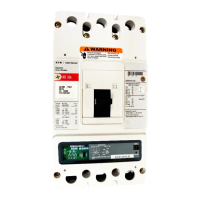
Figure 3. Installation of the Rating Plug and Mounting Screw
Wiring
The internal components of the breaker, and how they are wired out
to the breaker secondary contacts, are shown in the breaker master
connection diagram provided as Appendix C.
Plexiglass cover
A clear, tamper-proof, plexiglass door sits on the breaker cover. This
door allows the settings to be viewed but not changed, except by
authorized personnel. The plexiglass cover meets applicable tamper-
proof requirements. The cover is held in place by two cover screws.
Security is ensured by the insertion of a standard meter seal through
the holes in both of the cover retention screws. The plexiglass cover
has an access hole for the Step and Reset/Battery Test pushbuttons.
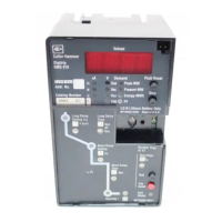
Ground Alarm/Power Supply Module
(520M/MC models only)
The Ground Alarm/Power Supply Module (see Figure 4) is an
optional accessory for the Digitrip 520M, 520Mi and is a required
accessory to enable communications on the Digitrip 520MC and
520MCi models. The module can be installed beneath the metal
mounting plate of the trip unit in the Magnum circuit breaker.
The module covers the following input voltage ratings: 120 Vac
(7802C83G11), 230 Vac (7802C83G12), 24–48 Vdc (7802C82G12),
and 125 Vdc (7802C82G13). The burden of the Power/Relay Module
is 10 VA.
Figure 4. Ground Alarm/Power Supply Module for the 520M or
520MC Trip Units

 Loading...