30
Instructional Leaflet IL70C1037H05
Effective October 2009
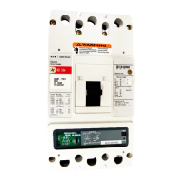
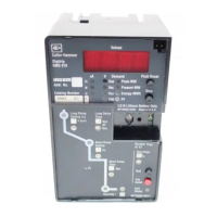
Digitrip models 520, 520i; and 520M, 520Mi,
520MC, 520MCi trip units for use only in
Magnum and Magnum DS circuit breakers
EATON CORPORATION www.eaton.com
Section 7: Frame ratings (sensor ratings
and rating plugs)
The frame rating of a circuit breaker is the maximum rms current it
can continuously carry. The maximum short-circuit current rating of
the circuit breaker is usually related to the frame rating as well.
A current value, (I
n
), that is less than the full frame rating may be
chosen to be the basis for the coordination of the protection function
of the breaker without affecting its short-circuit current capability.
For the Digitrip 520 family of trip units, this is implemented by
changing the current sensors and the corresponding rating plug.
These sensors and rating plugs are available in kit form.
The current sensor rating is the maximum current the circuit breaker
can carry with the specified current sensors installed. The sensor
rating can be the same or less than the frame rating, but not greater.
This value, (I
n
), is the basis for the trip unit current settings:
1. The Instantaneous and Ground Current Settings (if provided) are
multiples of (I
n
) (see Section 4).
2. The Long Delay Current Setting, (I
r
), is a fractional multiple of (I
n
):
Long Delay Current Setting = (I
r
) = LD x (I
n
) (see Section 4).
3. The Short Delay Current Setting is a multiple of (I
r
): Short Delay
Current Setting = SD x (I
r
) = SD x [LD x (I
n
)] (see Section 4).
m CAUTION
BEFORE YOU FIT THE RATING PLUG INTO THE TRIP UNIT, BE SURE TO
CHECK THAT EACH BREAKER POLE SENSOR RATING MATCHES THAT
PRINTED ON THE RATING PLUG DOOR. INSTALLING A RATING PLUG
THAT DOES NOT MATCH THE SENSOR RATING CAN PRODUCE SERIOUS
MISCOORDINATION AND/OR FAILURE OF THE PROTECTION SYSTEM.
ote:N Rating plugs from Digitrip models 210, 500, or 510 CANNOT be used
with 520 family model trip units.
Section 8: Record keeping
Use the forms shown in Figure 44 and Figure 45 for record
keeping. Fill in these forms, giving the indicated reference
information and initial time-current trip function settings. If desired,
make a copy of the form and attach it to the interior of the breaker
cell door or another visible location. Figure 46 provides a place for
recording test data and actual trip values.
Ideally, sheets of this type should be used and maintained by those
personnel in the user’s organization that have the responsibility for
protection equipment.
DIGITRIP
TRIP FUNCTION SETTINGS
Circuit No./Address
__________________
Breaker Shop Order Reference
_______________________
PER UNIT MULTIPLIERS
Rating Plug Amperes (I
n
)
__________________
I
r
Continuous Ampere Rating = LDS x I
n
___________________________
Trip
Function
Per Unit
Setting
Multi Ampere
Equivalent Setting
Time Delay
Inst. I
n
Long Delay I
n
Sec.
Short Delay I
r
Sec.
Ground Fault I
n
Sec.
Date________________ By __________________________________________
Figure 44. Typical Trip Function Record Nameplate
DIGITRIP
AUTOMATIC TRIP OPERATION RECORD
Circuit No./Address Circuit Breaker Shop Order Reference
Trip Function Settings Reference
Orig. 0 Rev. 1 Rev. 2 Rev. 3
Instantaneous
Long delay setting
Long delay time
Short setting
Short time
Ground fault setting
Ground fault time
Date of Trip Trip Mode
Indicator
Setting
Ref.
Setting
Change
Made
Investigated
By
Figure 45. Automatic Trip Operation Record

 Loading...