12
Instructional Leaflet IL70C1037H05
Effective October 2009
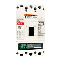
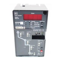
Digitrip models 520, 520i; and 520M, 520Mi,
520MC, 520MCi trip units for use only in
Magnum and Magnum DS circuit breakers
EATON CORPORATION www.eaton.com
m CAUTION
IF THE SENSOR CONNECTIONS ARE INCORRECT, A NUISANCE TRIP
MAY OCCUR. ALWAYS OBSERVE THE POLARITY MARKINGS ON THE
INSTALLATION DRAWINGS. TO ENSURE CORRECT GROUND FAULT
EQUIPMENT PERFORMANCE, CONDUCT FIELD TESTS TO COMPLY WITH
NEC REQUIREMENTS UNDER ARTICLE 230-95(C).
Source ground sensing
Depending upon the installation requirements, alternate ground
fault sensing schemes may be dictated (see Figure 11 and
Figure 12). The ground return method is usually applied when
ground fault protection is desired only on the main circuit breaker
in a simple radial system. This method is also applicable to double-
ended systems where a midpoint grounding electrode is employed.
For this mode of sensing, a single current sensor mounted on
the equipment-bonding jumper directly measures the total ground
current flowing in the grounding electrode conductor and all other
equipment-grounding conductors.
The settings shown in Table 3 will apply when the neutral
sensor is not the same as the frame rating in a ground return
sensing scheme.
Zero sequence sensing
Zero sequence sensing, also referred to as vectorial summation
(see Figure 13), is applicable to mains, feeders, and special
schemes involving zone protection. Zero sequence current
transformers (5.06 x 15.37 in. [128 x 390 mm] rectangular inside
dimensions) are available with 100:1 and 1000:1 ratios (styles
9253C07G01, G11).
Multiple source/multiple ground
A multiple source/multiple ground scheme is shown in Figure 14.
In this figure, a ground fault is shown that has two possible return
paths, via the neutral, back to its source. The three neutral sensors
are interconnected to sense and detect both ground fault and
neutral currents.
Contact Eaton for more details on this scheme.
Ground fault settings
The adjustment of the ground fault functional settings (FLAT
response or I
2
t) is discussed in Section 4. The effect of these
settings is illustrated in the ground fault time-current curve
referenced in Section 9. Applicable residual ground fault pickup
settings and current values are given in Table 4, as well as in the
ground time-current curve.
Table 4. Ground (Earth) Fault Current Settings
Ground Fault Current Settings (Amperes)
a
Installed Sensor and Rating Plug (Amperes) I
n
0.25 0.30 0.35 0.40 0.50 0.60 0.75 1.0
200 50 60 70 80 100 120 150 200
250 63 75 88 100 125 150 188 250
300 75 90 105 120 150 180 225 300
400 100 120 140 160 200 240 300 400
600 150 180 210 240 300 360 450 600
630 158 189 221 252 315 378 473 630
800 200 240 280 320 400 480 600 800
1000 250 300 350 400 500 600 750 1000
1200 300 360 420 480 600 720 900 1200
1250 312 375 438 500 625 750 938 1250
1600 400 480 560 640 800 960 1200 1600
b
2000 500 600 700 800 1000 1200 1500
b
2000
b
2500 625 750 875 1000 1250 1500 1875 2500
3000 750 900 1050 1200 1500
b
1800
b
2250
b
3000
b
3200 800 960 1120 1200 1600
b
1920
b
2400
b
3200
b
4000
c
1000 1200 1400
b
1600
b
2000
b
2400
b
3000
b
4000
b
5000
c
1250
b
1500
b
1750
b
2000
b
2500
b
3000
b
3750
b
5000
b
6000 1500
b
1800
b
2100
b
2400
b
3000
b
3600
b
4500
b
6000
b
6300
c
1575 1890 2205 2520 3150 3780 4725 6300
a
Tolerance on settings are ±10% of values shown.
b
On models 520 LSIG, 520M, and 520MC LSIG, the shaded values are set to a maximum trip value of 1200A for NEC.
c
See page 17.

 Loading...