Effective 8/13/99
Page 10
I.L. 70C1037H02
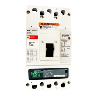
rating specified on the plug label. The current sensor
rating can be viewed through openings in the back of the
breaker.
2.5 Current Sensors (Magnum Frames greater than 3200A)
The six (3-pole) or eight (4-pole) current sensors installed
in the circuit breaker are located on the lower conductors.
The poles are paralleled and the corresponding current
sensors are also paralleled (see Figure 2.3). For ex-
ample, a 4000A breaker phase rating has two 2000:1
current sensors wired in parallel, which provides an
overall ratio of 4000:2. The auxiliary current transformers
have a ratio of 20:1 for this size breaker which further
steps down the rated current to 100 milliamperes and is
equivalent to 100% (
I
n) to the Digitrip.
3.0 PRINCIPLES OF OPERATION
3.1 General
The Digitrip DT20 family of trip units is designed for
industrial circuit breaker environments where the ambient
temperatures can range from –20° C to +85° C but rarely
exceed 70° to 75° C. If, however, temperatures in the
neighborhood of the trip unit exceed this range, the trip
unit performance may be degraded. In order to insure that
the tripping function is not compromised due to an over-
temperature condition, the Digitrip 520 family microcom-
puter chip has a built-in over-temperature protection
feature, factory set to trip the breaker if the chip tempera-
ture is excessive. On the 520 family, if over-temperature
is the reason for the trip the red Long Delay Time LED will
flash.
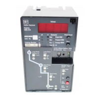
The Digitrip uses the Cutler-Hammer custom-designed
SµRE+chip™, an integrated circuit that includes a
microcomputer to perform its numeric and logic functions.
The principles of operation of the trip unit are shown in
Figure 3.1.
In the Digitrip DT20 family of trip units, all sensing and
tripping power required to operate the protection function
is derived from the current sensors in the circuit breaker.
The secondary currents from these sensors provide the
correct input information for the protection functions, as
well as tripping power, whenever the circuit breaker is
carrying current. These current signals develop analog
voltages across the current viewing resistors. The result-
ing analog voltages are digitized by the SµRE+chip™.
The microcomputer continually digitizes these signals.
This data is used to calculate true RMS current values,
which are then continually compared with the protection
function settings and other operating data stored in the
Table 2.2 Ground (Earth) Fault Current Settings
Ground Fault Current Settings
(Amperes)
1
Installed
Sensor/
Rating Plug
200 50 60 70 80 100 120 150 200
250 63 75 88 100 125 150 188 250
300 75 90 105 120 150 180 225 300
400 100 120 140 160 200 240 300 400
600 150 180 210 240 300 360 450 600
630 158 189 221 252 315 378 473 630
800 200 240 280 320 400 480 600 800
1000 250 300 350 400 500 600 750 1000
1200 300 360 420 480 600 720 900 1200
1250 312 375 438 500 625 750 938 1250
1600 400 480 560 640 800 960 1200 1600
2
2000 500 600 700 800 1000 1200 1500
2
2000
2
2500 625 750 875 1000 1250 1500 1875 2500
3000 750 900 1050 1200 1500
2
1800
2
2250
2
3000
2
3200 800 960 1120 1200 1600
2
1920
2
2400
2
3200
2
4000
3
1000 1200 1400
2
1600
2
2000
2
2400
2
3000
2
4000
2
5000
3
1250
2
1500
2
1750
2
2000
2
2500
2
3000
2
3750
2
5000
2
6300
3
1575 1890 2205 2520 3150 3780 4725 6300
1. Tolerance on settings are ±10% of values shown.
2. On Models 520 LSIG and 520M LSIG, the shaded values are set to a maximum
trip value of 1200 amperes for NEC.
3. See Section 2.5.
2.4 Current Sensors (Magnum Frames less than or equal to
3200A)
The three (3-pole) or four (4-pole) primary current sensors
are installed internally in the circuit breaker on the lower
conductors of the breaker. The current sensor rating
defines the breaker rating (
I
n). For example, 2000A:1A
sensors are used on a 2000A rated breaker. There are
four auxiliary current transformers with a ratio of 10:1
which further step down the rated current to 100 milliam-
peres, which is equivalent to 100% (
I
n) to the Digitrip.
The primary current sensors produce an output propor-
tional to the load current and furnish the Digitrip DT20
family with the information and energy required to trip the
circuit breaker when functional protection settings are
exceeded.
If a set of current sensors with a different ratio are in-
stalled in the field, the rating plug must also be changed.
The associated rating plug must match the current sensor
Courtesy of NationalSwitchgear.com

 Loading...