26
Operating Manual for Series NRX
Trip Units - Digitrip™ 520/520M
EATON www.eaton.com
Instruction Leaet IL01301051E
effective September 2013
When the module is installed and powered with 24 Vdc, the Digitrip
520M will be able to communicate with this module via contacts
CMM1, CMM2, CMM3, and CMM4. For communication to the
Modbus or INCOM network, a plug-in connector on the top of this
module provides the required network connections. For additional
information on each of the communication modules please reference
the following instruction leaflets:
IL01301033E (ICAM)
IL01301034E (MCAM)
IL01301035E (PCAM)
IL01301052E (ECAM)
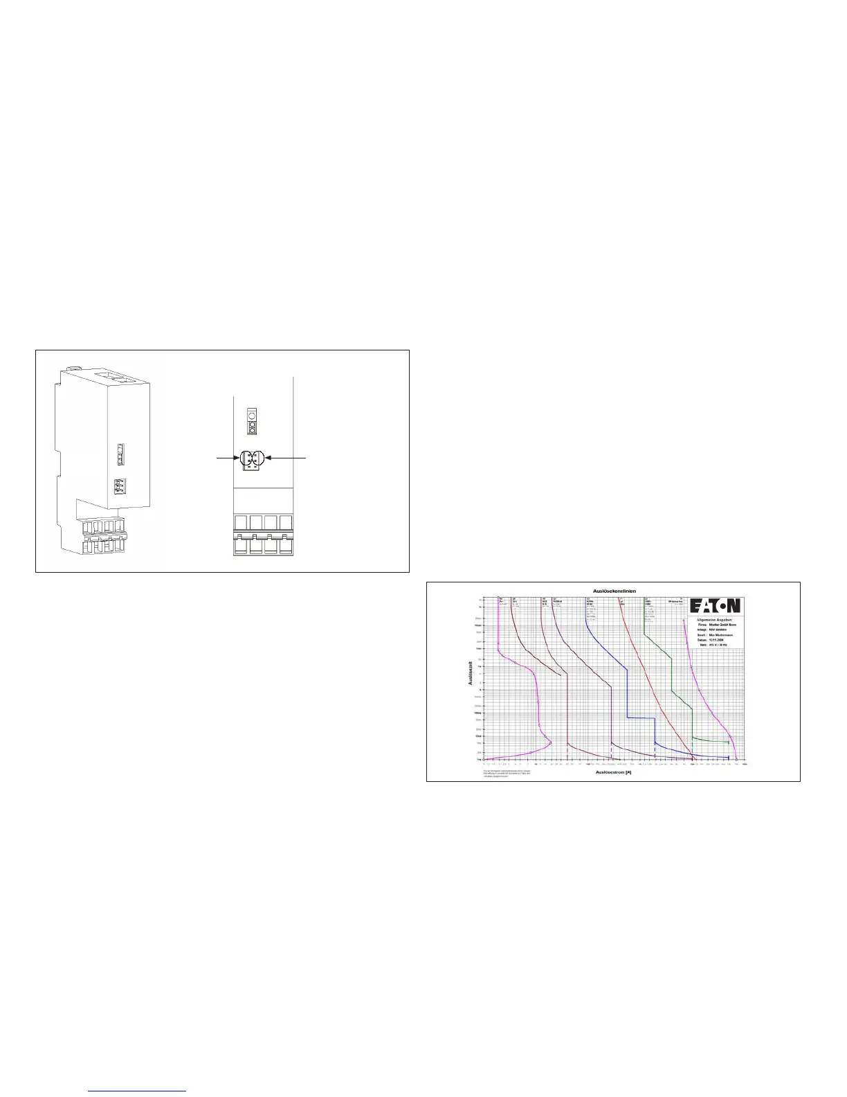
ote:N When using a Communication Module, the enabling of source ground
mode is done via the position of the jumper located on this module.
Figure 22.
Jumper Plug
Enable for
Source Sensing
Jumper Plug
Enable for
Communication
Control
Communication Module
Section 9: References
Series NRX circuit breakers
MN01301001E NRX Circuit Breaker Manual - NF
MN01301003E NRX Circuit Breaker Manual - RF
IL70C1592 Rating Plug
IL01301031E Source Ground/ Zero Sequence Sensor
IL01301032E Neutral Current Sensor - NF
IL01301046E Neutral Current Sensor - RF
IL01301067E Functional Test Kit
TD01301014E Series NRX Circuit Breaker
Wiring Diagrams
Time-current curves
The time-current curves are listed below for particular frame models.
All protection function time-current settings should be made by
following the recommendations of the specifying engineer in charge of
the installation.
Type NF Frame (IZMX16/IZM91)
AD01301004E Application Data
•
Long Delay
•
Long Delay and Short Delay
•
Instantaneous
•
Ground Fault
•
Maintenance Mode
Type RF Frame (IZMX40/IZM95)
AD01301004E Application Data
•
Long Delay
•
Long Delay and Short Delay
•
Instantaneous
•
Ground Fault
•
Maintenance Mode
Use the following to access Time Current Curves. Go to Eaton’s Web
site: http://www.eaton.com and search “NRX Digitrip 520 Curves”.
All Series NRX publications can be found on-line at
http://www.eaton.com by searching for the respective publication
number.
Curve Select
Figure 23. Curve Select
The “CurveSelect” software tool enables the representation of tripping
characteristics which correspond to the individual switch and relay
settings using Microsoft Excel®. In many electrical power networks
the protective devices are connected in series. The program makes it
possible to represent and evaluate all curves at the same time with a
minimum of effort.
You can download the tool for free at www.eaton.com.