22 OPERATION AND INSTALLATION INSTRUCTIONS MN280075EN July 2018
Form 6 microprocessor-based rack-mount recloser control
NOTICE
External leads must be shielded and the shield must be
grounded at both ends. Terminate each lead with a 320
VAC, 150 Joules metal oxide varistor (MOV), or equivalent,
at the remote end. Attach MOVs between the leads
and ground. Failure to properly shield and protect leads
can result in equipment damage and/or unintentional
operation.
IMPORTANT
Shielding and Surge Protection of Supervisory Cables
All supervisory operation and control monitor leads must
be protected within shielded cables. Refer to Figure15 or
Figure16 as appropriate.
CI4
TB3
1
3579 11 13 15 17 19 21
CI5
CI6
CI7 CI8
CI9
CI10
CI11
CO5
CO6
TB4
2
46 810121416
18
20
CI4 CI5 CI6 CI7 CI8 CI9
CI10
CI11
CO5
CO6
13
5
7911 13
CO7 CO8
CO9 CO10 CO11
CO12
2
46
8
10
12
CO7 CO8 CO9
CO10
CO11
CO12
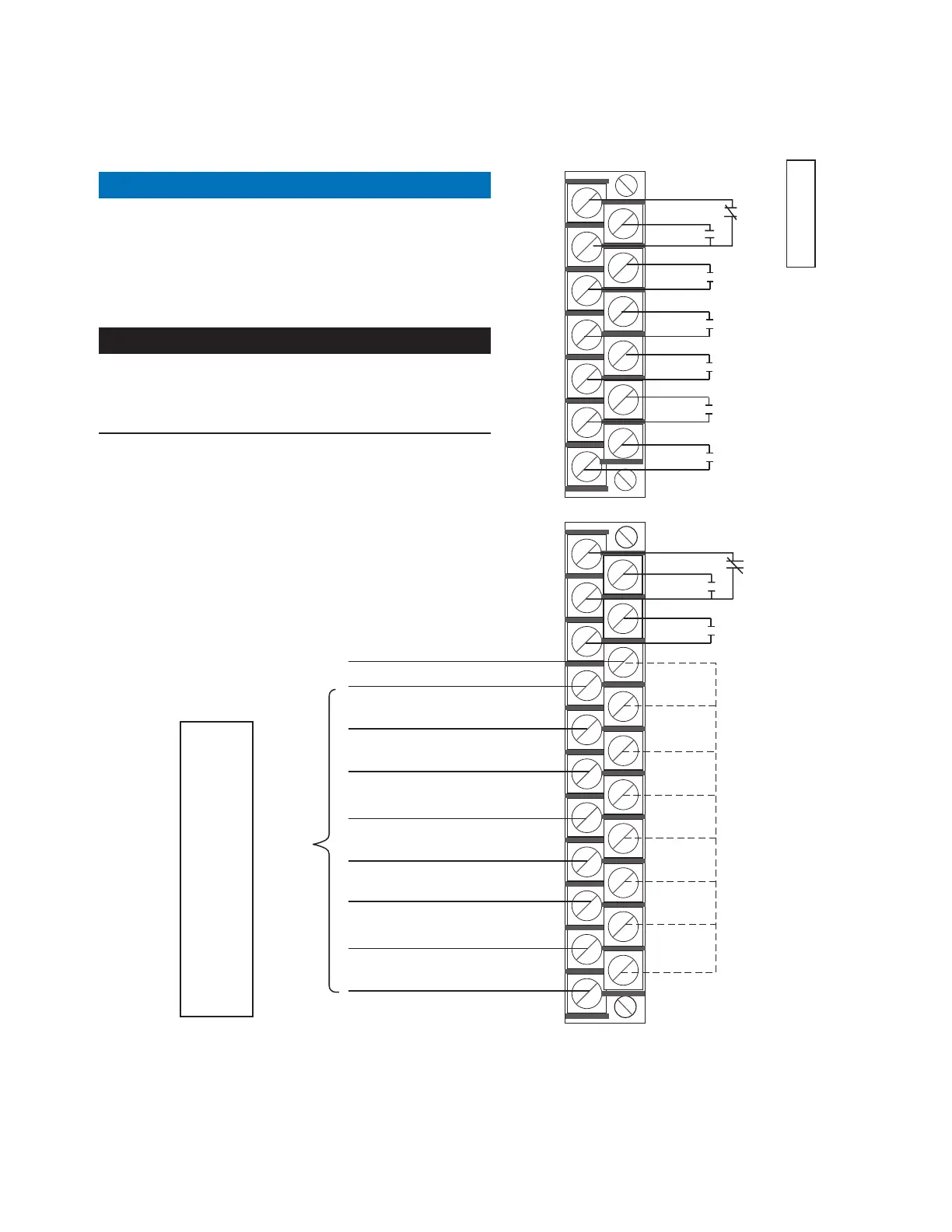
Supervisory Ground Trip Block
Supervisory Reset Targets
Supervisory Non-Reclose
Not Assigned
Remote Alternate Profile 2
Remote Alternate Profile 1
Remote Alternate Profile 3
Non-Reclosing
Status
(Normal
Reclose)*
Remote Normal Profile
Alarms
Status
(No Alarms)*
Alternate
Profile 1
Status
(Not in
Alt 1
Profile)*
Normal
Profile
Status
(Not in
Normal
Profile)*
Alternate
Profile 2
Status
(Not in
Alt 2
Profile)*
Frequency
Alarm
(Frequency
Normal)*
Alternate
Profile 3
Status
(Not in
Alt 3
Profile)*
Voltage
Alarm
(Voltage
Normal)*
*Relay Contacts shown
for Indicated Status
Customer Wiring
Remote/Supervisory Common
Customer-Supplied
Voltage Inputs**
**Whetting voltage is available from the
Form 6 Recloser Control on Terminal Block
TB5. Refer to Figure 16.
**Whetting voltage is also available from the
Form 6 Recloser Control on Terminal Block TB5.
Refer to Figure15 or Figure16, as appropriate.
Figure14. Form 6 recloser control discrete interface board accessory and default configurations. These default
contact input/outputs are completely configurable via the idea workbench
 Loading...


