4 OPERATION AND INSTALLATION INSTRUCTIONS MN280075EN July 2018
Form 6 microprocessor-based rack-mount recloser control
Front panel text messaging
The LCD messages are accessed from the front panel by
following the Text Messages menu path. This menu displays
any active user-configured text messages.
Up to fourteen user-configurable text messages can be
programmed via the Idea Workbench. Refer to Service
Information S280-70-4 (ProView 4.X.X) or S280-70-21
(ProView 5.X.X) Form 6 Control Programming Guide for
information on programming the text messages.
These text messages appear on the front panel LCD and
can be programmed to appear for alarm or other conditions.
Text messages displayed on the front panel are limited to
four lines of 20 characters each (including spaces). Text
messages can also be accessed by pressing the LAMP
TEST one-touch analysis key on the front panel.
Programming panel
The Programming panel has the following sections:
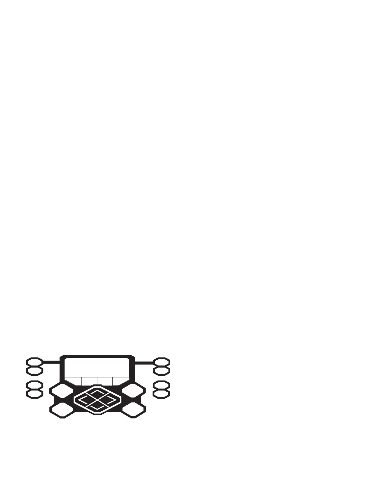
One-touch analysis keys
There are eight analysis keys (Figure3) that allow
one-button access to a variety of control and monitoring
functions that appear in the LCD display. Pressing these
buttons causes the following information to display or
function to occur:
ote:N When pressing a membrane pushbutton, always
press and hold for 0.5 seconds to ensure the button
press is recognized by the device.
METERING: Displays the systems instantaneous metering
values for current and voltage on the LCD display.
RESET TARGETS: Resets the fault target indicators on the
operator panel.
EVENTS: Displays the last 25 events from the Sequence of
Events log.
LAMP TEST: All operator panel LEDs are illuminated for
verification of proper connection and operating status of all
indicator lights. All status indicators will then return to their
previous state. While in the LAMP TEST mode, the control
response to operator panel keys is disabled, except for the
TRIP (LOCKOUT), CLOSE, and HOT LINE TAG switches.
SETTINGS: Displays recloser settings on the LCD display.
METERING
RESET
TARGETS
EVENTS
LAMP TEST
MENU
ENTER
+
—
SETTINGS
OPER
COUNTER
ALARMS
CHANGE
F1 F2 F3 F4
Figure3. Analysis keys, LCD display, LCD menu function
keys, and cursor movement arrows
OPER COUNTER: Displays the total number of trip
operations and target counters for each A, B, and C Phase;
Ground, and Sensitive Ground on the LCD display.
ALARMS: Provides status information on the LCD display
for all recloser alarms.
CHANGE: Allows the user to change the state of the control
functions on the operator panel function keys.
ote:N The CHANGE mode is a ten second period in which
one function setting can be changed. If no change
is made in that time, the control returns to the
currentsetting.
LCD Display
The LCD Display is a backlit 4-line, 20-character display that
provides extensive distribution system, recloser, and control
status information using a minimum of eight navigation
keypads (Figure3).
ote:N The LCD display panel contrast is field-adjustable to
allow for various mounting heights and applications.
Press the MENU key and then press the (+) or (–)
key to increase or decrease the contrast.
The four LCD navigation buttons are as follows:
MENU Identifies the LCD Display menu options.
ENTER Selects a menu option.
+ Increases value selection.
– Decreases value selection.
The four LCD menu function keys activate specific menu
commands. When a command appears in the LCD display
directly above one of the four LCD menu function keys, the
user can press the key to accept/select the command.
The four LCD menu function keys are as follows:
F1 F2 F3 F4
The four cursor movement arrows allow movement in the
following directions:
Moves the cursor left.
Moves the cursor right.
Moves the cursor up one line.
Moves the cursor down one line.
Status indicator LEDs
The status indicator LEDs (Figure4) in the Programming
section of the Operator Panel give instant information on
the control and recloser status:
All of the default status indicators LEDs (except for
CONTROL OK, CONTROL POWER, and ALARM) can be
reconfigured via the Idea Workbench. Refer to Service
Information S280-70-4 (ProView 4.X.X) or S280-70-21
(ProView 5.X.X) Form 6 Control Programming Guide for
additional information.
 Loading...


