Catalog data MN650002EN
Effective February 2019
Deadbreak apparatus connectors
Step 9.
Install shear bolt connector
ote:N Refer to the separate installation instructions
supplied with the shear bolt connector.
•
Install centering ring.
• Refer to Figure 11 and Table 1 to determine what size
conductors require a centering ring and the correct
color to use.
•
Wire brush conductor (aluminum only).
•
Immediately insert the conductor completely into the
barrel of the lug and rotate connector to distribute
inhibitor.
•
Align flats of connector and apparatus bushing for
minimum conductor strain.
ote:N Connector must be fully seated on cable conductor.
•
With an Allen hex key as specified in Table 2 screw in bolt
No. 1 until it breaks off smoothly. Proceed with bolt No.
2 in a similar way. If the lug has more than two (2) bolts,
continue with bolt No. 3 and bolt No. 4, (not shown in
Figure 11). See Figure 11 for tightening sequences.
•
Once all the bolts have broken off, smooth any rough
edges with a file and install the covering caps. Carefully
clean off any filings.
•
Wipe excess inhibitor from connector and adapter
surfaces.
Step 10.
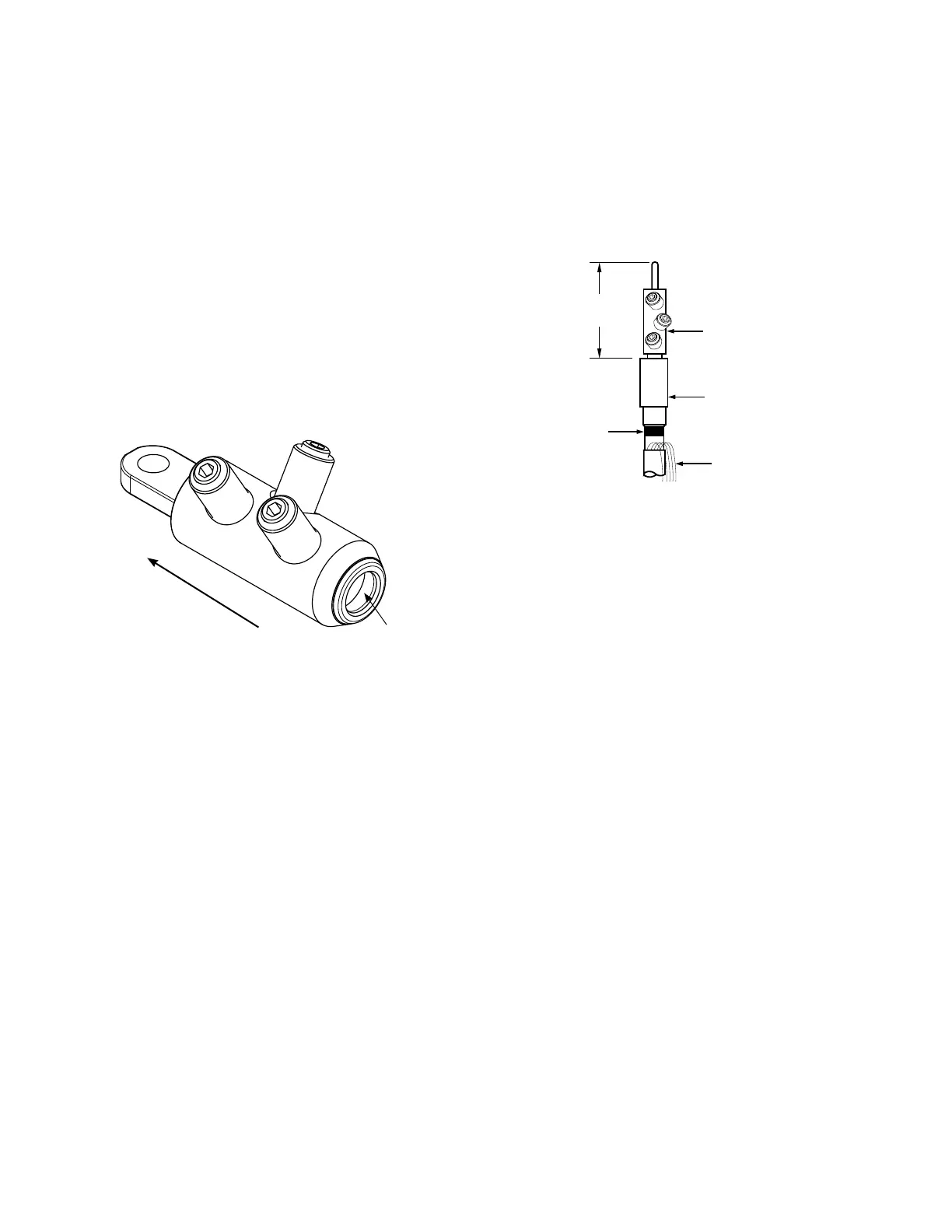
Check di men sions
•
Check length from end of com pres sion con nec tor to top
of cable adapter.
•
Length should be no longer than "E" dimension. (Re fer to
Fig ure 12 and Table 2.)
Install BOL-T T-body with mating parts
Step 11.
Install DT635 T-body
•
Clean and lubricate outside of cable adapter with lubricant
supplied.
•
Clean and lubricate inside of T-body with lubricant sup-
plied.
ote:N If test point T-body is used, insure test point is
opposite front plate side of T-body.
•
Without moving the cable adapter, slide T-body onto cable
adapter until compression connector eye is centered in
600 A interfaces. (Refer to Figure 13.)
ote:N The end of the cable adapter must line up with
the top edge of the tape marker after T-body
assembly. Refer to Figure 10.
•
Remove tape marker from cable.
Figure 12. Line illustration for dimensional check.
Shear bolt connector
E
(See Table 2)
Tape
marker
Cable adapter
Concentric neutral
wires
Figure 11. Mechanical lug tightening sequence.
Bolt 2
Bolt 1
Bolt 3
Start with Bolt 1
Centering Ring
6
600 A 35 kV class BOL-T connector assembly installation instructions for MN650002EN February 2019
 Loading...


