Catalog data MN650002EN
Effective February 2019
Deadbreak apparatus connectors
Step 2.
Remove concentric neutral wires or jacket
ote:N Care should be taken to not cut or score the
neutral conductors when cutting the cable jacket.
•
Measure reference length "B" from end of cable. (Refer to
Figure 4 and Table 2 to determine variable "B" length.
• For jacketed neutral cable, remove jacket to "B"
dimension.
• For unjacketed neutral cable, bind neutral wires using
three (3) wraps of tape at "B" dimension.
•
Pull back concentric neutral wires. Allow enough extra
concentric neutral wires to connect to ground after
installation and allow movement to insulated standoff
bushing.
Step 3.
Remove insulation shield
•
Remove insulation shield length "C" from end of cable.
(Refer to Figure 5 and Table 2 to determine variable "C"
length.)
ote:N Do not cut or nick insulation.
Step 4.
Put tape marker in place
•
Measure 1" (25 mm) from end of insulation shield. (Refer
to Figure 5.)
•
Wrap two turns of tape to serve as marker for cable
adapter location.
Step 5.
Remove conductor insulation
ote:N Do not pencil cable.
•
Remove insulation exposing bare conductor to length of
"D". (Refer to Figure 6 and Table 2 to determine variable
"D" length.)
ote:N Do not unwind conductor strands.
Step 6.
Bevel insulation
•
Remove sharp edge of insulation by beveling at a 45°
angle for approximately 1/4" (6 mm). (Refer to Figure 7.)
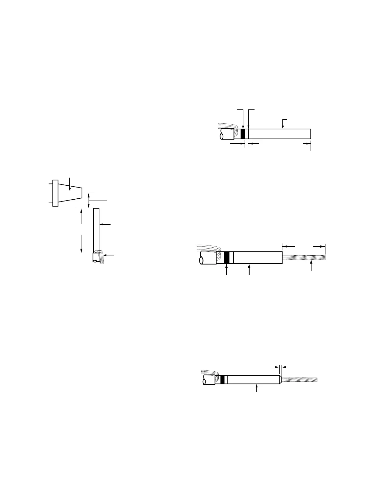
Figure 7. Line illustration of insulation bevel.
Bevel
Insulation
•
1/4"
(6 mm)
Figure 6. Line illustration of bare conductor length.
"D"
(See Table 2)
Tape Marker
Bare Conductor
Insulation
Figure 4. Line illustration of removing concentric neutral
wires.
Bushing
Cable
"A"
(See Table 2)
"B"
(See Table 2)
Concentric Neutral
Wires
Figure 5. Line illustration of cable stripback.
"C"
(See Table 2)
1"
(25 mm)
Tape Marker Insulation Shield
Insulation
4
600 A 35 kV class BOL-T connector assembly installation instructions for MN650002EN February 2019
 Loading...


