DRAFT - 26 March 2015 DRAFT - 26 March 2015
SM45-55-SAD Rev 3
1110
7.2 Appendix B: Proof Test Procedure, MTL45/5500 Digital Output Modules
Example MTLx521 Proof Test Procedure
Solenoid driver module Proof Test Procedure:
1. System - Normal operation test
2. Input /Output characteristic functional safety test
3. System - Normal operation test
1. System - Normal operation test
Make sure that the module to be tested is operating normally in the target system, without errors and in energised
mode. If the module is connected in a faulty or de-energised loop, restore normal fault free and energised
conditions before testing.
2. Input/Output characteristic functional safety test
Observe normal anti-static precautions when handling equipment during device testing.
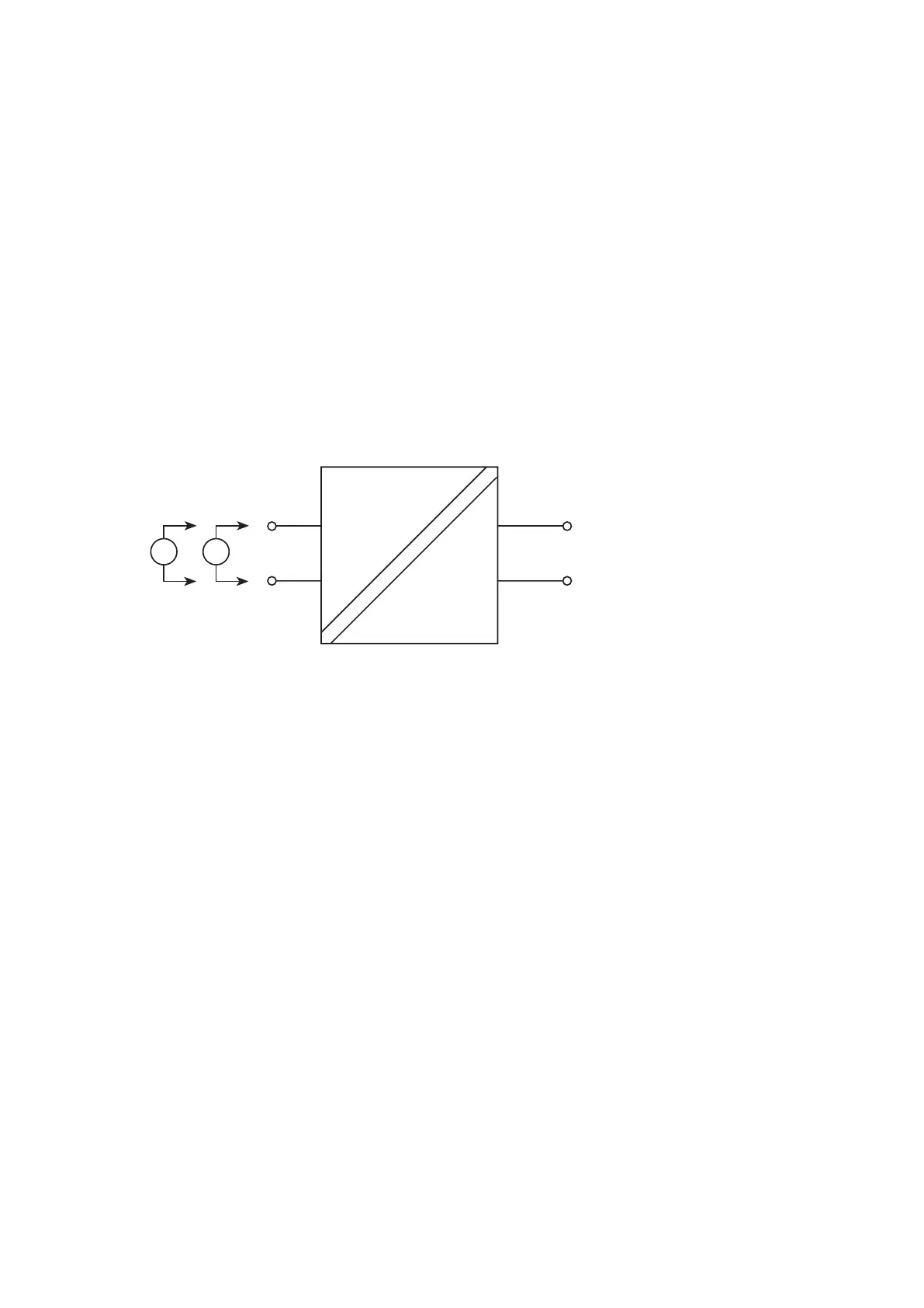
Remove the unit from the target system and connect as shown in Figure 1. Please note, that it is acceptable to
leave the unit in the target system, when it is secured, that the terminals are disconnected from the system and
available for test. Alternatively, for the backplane mounted MTL4521 modules, use a separate backplane for this
purpose to facilitate access to the power and output connections.
a) Loop powered modules: MTL4521, 4521L, 5521, 5522, 4523L, 5525
Figure 1 Basic test arrangement - loop powered
1 Connect a voltmeter between the + & - output terminals of the module, observing polarity.
2 Apply 24V dc between the input drive terminals.
3 The voltmeter on the output terminals should indicate a value between 22.2 and 24 volts.
4 Switch off the power to the module.
5 Connect an ammeter between the + and – output terminals of the module, observing polarity.
6 Apply 24V dc between the input drive terminals.
7 The ammeter should indicate a value of at least 48mA and a maximum of 60mA (76mA for MTL5522)
Operate the test sequence and confirm expected operation of the module.
It is recommended that the results are recorded in a table such as that shown on page 11.
+
–
Vs+
Vs–
i/po/p
V
A
 Loading...