8
TM293 MEDC DB3BM UL Technical Manual
SOUNDER/HORN – DB3BM UL TM293.A August 2022 www.eaton.com
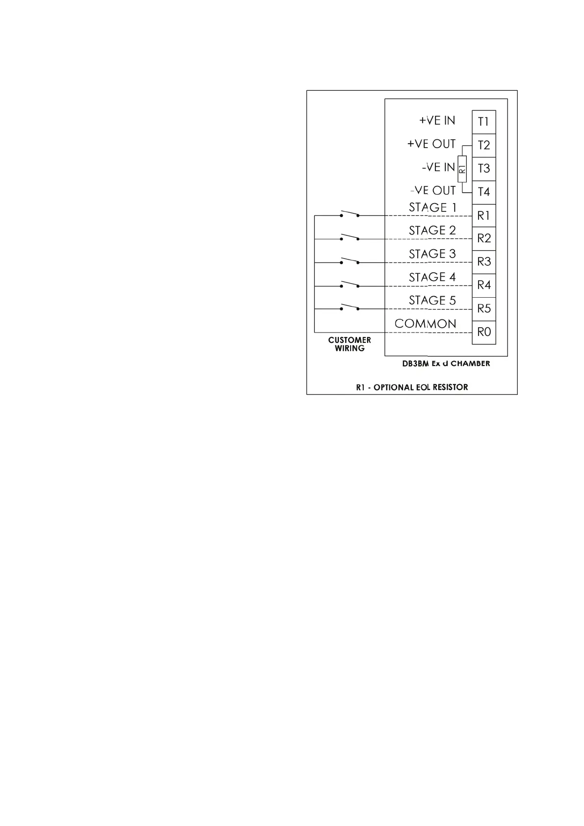
DC input with voltage free stage activation
wiring details (Type 6)
Connect the positive (+ve) and negative (-ve) supply wires
to the terminals as detailed in the wiring diagram. When
power is applied to the unit, no tone will be produced
initially. Connect wires and remote switches to terminals
R0 to R5 as shown. When the switch connected to R1 is
closed, the stage 1 tone will be produced as selected by
the 5-way DIP switch on the electronics assembly. When
any of the other switches connected to R2 to R5 is closed,
the pre-selected tone for stages 2 to 5 are produced. See
tone table 2 for details of pre-selected tones.
ote: N Closing more than one switch at a time will result in
no tone being produced.
If a resistor (R1) is fitted, monitoring functionality is
obtained when the supply polarity is reversed.
 Loading...