2
1.2 Features
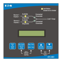
There are two types of features incorporated into the RAC: Status and Control. Below
are lists of each:
Status Type
• S1 & S2 Available
• S1 & S2 Connected
• S2 Connected Alarm
• Source 1 Data Information
• Source 2 Data Information
• Non-Auto Status
• Engine Test Status
• History of Alarm
Control Type
• Go to Source 2 (Emergency)
• Go to Source 2 Abort
• Engine Test
• Engine Test Abort
• Silence Alarm
• Bypass TDNE/TDEN
• Manual Retransfer
1.3 Set-up and Wiring
The RAC requires 24VDC power with a maximum current of 125 mA (See “A” below).
There is a terminal block connector on the back of the unit to install wires for the
power. The software comes preloaded onto the unit, and should require no user
programming.
Communication with the ATS controller is accomplished via Modbus RS-485 serial
network to the gateway. Drawing 66A8395E shows the wiring of the unit, which
includes the power connection and the communication daisy chain network. The
cable used should have two insulated wires and one ground connected to the shield of
the cable. The recommended cable is a CAT5E type but there are many similar
shielded cables that can be used. The drawing also shows the connection between
multiple controllers and the PXG-400E gateway. The gateway connects to the HMI’s
LAN port using a standard Ethernet CAT5E cable.
Note that multiple gateways may be connected to a single HMI unit over Ethernet to
further expand the communication flexibility of the system. Drawing 66A8395EM
should be referenced for wiring of multiple gateways.

 Loading...


