Do you have a question about the Eaton VICKERS SystemStak and is the answer not in the manual?
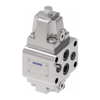
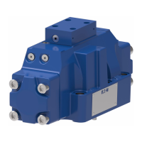
SystemStak valves create compact hydraulic systems by sandwiching specific function valves.
SystemStak valves eliminate intervalve piping, reducing installed costs compared to conventional valves.
Internal passages and mounting surfaces meet international standards for easy integration.
Internal parts made from hardened steel in ductile iron bodies ensure reliability and accessibility.
SystemStak circuitry uses specific symbols, with flow paths passing through each valve.
Two-stage adjustable pressure relief valves limit maximum pressure using integral relief valve elements.
Two-stage valves are represented as single-stage models for simplicity in functional symbols.
Defines the structure and options for ordering Relief Valves.
Describes the second line of dual models for relief valves, detailing options and usage.
Presents pressure override performance data for PT models at max settings with mineral oil.
Provides overall dimensions for relief valves.
Details adjustment procedure for type W adjuster, including slackening locknut and turning screw.
Single-stage valves operating by pressure on spool end, acting against spring for adjustment mechanism.
Provides functional symbols for DGMR, DGMX, and DGMR1 valve types.
Defines the model code structure for DGMR, DGMX valves, defining types, ports, and options.
Presents performance data for DGMX and DGMR1 valves.
Details typical leakage flow at 250 bar inlet pressure for DGMX valves under dead head conditions.
Explains that effective reduced pressure equals adjustment setting plus back-pressure in line T.
Provides installation dimensions for DGMR and DGMX valve types.
Details adjustment procedure for type W adjuster, including slackening locknut and turning screw.
Valves allowing free flow in one direction; flow in the opposite direction is not possible.
Illustrates functional symbols for direct check valves DGMDC-3-X and DGMDC-3-Y.
Defines the model code structure for direct check valves, including direction of flow and check location.
Graph showing pressure drop for free flow through check valves with different spring options.
Specifies internal leakage rate for closed check valves at 250 bar.
Shows installation dimensions for various DGMDC-3 valve types.
Valves providing pilot-operated check functions, with pilot supply from the opposite service line.
Shows functional symbols for pilot operated check valves DGMPC-3.
Defines the model code structure for pilot operated check valves, including decompression and function options.
Pressure drop data for flow paths A1 to A or B1 to B, and A to A1 or B to B1 with check valve pilot-operated.
Details pilot area ratios and formulae for calculating pilot pressure to open valve elements.
Shows installation dimensions for DGMPC-3 valve configurations.
Valves regulating flow via an adjustable orifice, not pressure compensated, dependent on pressure drop.
Shows functional symbols for flow restrictor valves DGMFN-3.
Defines the model code structure for flow restrictor valves, including direction, location, and type of control.
Graphs showing pressure drop for Type "1" and Type "2" needles with varying turns of adjuster.
Shows installation dimensions for DGMFN-3 valve configurations.
Details adjustment procedure for type W adjuster, including slackening locknut and turning screw.
Information on mounting bolts, subplates, and manifold blocks for SystemStak valves.
Specifies temperature limits, compatible fluids, and filtration requirements.
Details pressure drop at other viscosities and types H/K adjusters.
Covers spare parts, warranty, repair, and ordering procedures.
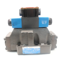
Describes solenoid-operated directional control valves, their benefits, and applications.
Highlights performance aspects of DG4V-3 and DG4V-3S models, including flow, pressure, and interface standards.
Lists key features and benefits, such as high pressure/flow capabilities and reliable operation.
Explains how valve body and spool optimization leads to low energy consumption and efficiency.
Discusses design of spring and solenoid forces ensuring spool selection under extreme conditions.
Describes the manual override seal design preventing bore damage and messy oil drips.
Details conduit box design and wet-armature solenoid for easy servicing.
Explains surge suppression to prevent coil damage and increase switch life.
Details performance characteristics, including pressure, flow, and mounting interface.
Specifies ISO 4401, ANSI/B93.7M, CETOP, and DIN standards for mounting.
Covers maximum pressure, flow, valve function, electrical connections, and operating considerations.
Provides fluid temperature limits and ambient temperature limits for the valves.
Illustrates functional symbols for U.S. solenoid standards, including double/single solenoid valve configurations.
Illustrates functional symbols for European solenoid standards, including double/single solenoid valve configurations.
Explains solenoid identity conventions for U.S. and European standards, relating to port connection.
Defines model code elements from Series to Spool Indicator Switch.
Defines model code elements from Coil Type to Coil Rating.
Defines remaining model code elements from Port T code to Port Restrictor Plugs.
Specifies pressure limits, flow ratings, and duty factor for valve models.
Details protection types, coil specifications, and permissible voltage fluctuations.
Lists spool displacement times and power consumption for AC and DC solenoids.
Details input/output specs, plug connections, and wiring for DG4V-3 position indicator models.
Specifies voltage and current for micro-switch types S3, S4, S5.
Presents performance data graphs for DG4V-3S AC solenoid valves.
Presents performance data graphs for DG4V-3S DC solenoid valves.
Presents performance data graphs for DG4V-3 AC solenoid valves.
Presents performance data graphs for DG4V-3 DC solenoid valves.
Details flow limitations for specific spool types and usages.
Graphs showing pressure drops for DG4V-3S and DG4V-3 models.
Table detailing pressure drops in offset positions for different spool/spring codes.
Provides dimensions for models using ISO 4400 connectors.
Details installation dimensions and application for water-resistant and latching manual overrides.
Provides dimensions for models with "F" type coils, including conduit box.
Shows dimensions for specific DG4V-3 models with LVDT or mechanical switches.
Table for selecting restrictor plugs based on code, orifice diameter, and part number.
Describes terminal strip, conduit box, Insta-Plug, PA, and PBW connectors.
Details NFPA connector types, including 3-pin and 5-pin connectors and their wiring.
Provides details on DIN 43650 connectors, including voltage, part numbers, and orientation.
Explains surge suppression devices and presents valve shift/dropout times.
Describes ranges of subplates and auxiliary plates for size 3 valves.
Shows installation dimensions for blanking, crossover, and tapping plates.
Details installation dimensions for adaptor plates with metric and UNC bolt tapping.
Shows mounting surface dimensions and bolt details.
Shows dimensions for DGVM single station subplates with rear ports.
Shows dimensions for DGMS single station subplates with side ports.
Shows installation dimensions for DGMS multi-station subplates.
Details requirements for a machined mounting pad when a subplate is not used.
Lists inch and metric bolt kits with part numbers and sizes.
Refers to service drawing for spare parts and lists kit numbers for seal kits.
Provides part numbers for AC and DC solenoid coils.
Lists approximate mass and provides guidance on mounting attitude.
Specifies ambient temperature range and recommended fluid temperatures.
Explains fluid cleanliness requirements and recommended levels.
| Category | Control Unit |
|---|---|
| Brand | Eaton VICKERS |
| Product Family | SystemStak |
| Port Size | NG06, NG10 |
| Maximum Pressure | 350 bar (5076 psi) |
| Operating Temperature Range | -20°C to +70°C (-4°F to +158°F), depending on seal material |