10 EATON Vickers Solenoid Operated Directional Valves Product Catalog V-VLDI-MC011-E September 2008
Performance Data
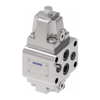
DG4V-3 models (high performance)
Graph 4
AC solenoid valves with:
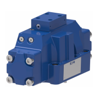
Graph 5
AC solenoid valves with dual-
frequency coils operating at 60 Hz
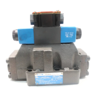
Graph 6
DC solenoid valves
Spool/ Graph Graph Graph
spring 4 5 6
code curve curve curve
0A(L) 2 2 3
0B(L) & 0C, 0F 1 1 2
2A(L) 2 2 3
2B(L) & 2C, 2F 1 1 1
2N 1 1 2
6B(L) & 6C, 6F 6 5 6
7B(L) & 7C, 7F 1 1 2
8B(L) & 8C 5
s 4 s 5 s
22A(L) 8 7 8
22B(L) & 22C 7 6 7
24A(L) 9 8 5
33B(L) & 33C 4 3 4
34B(L) & 34C 4 3 6
52BL, 52C, 6 5 6
56BL & 56C 6 5 6
66B(L) & 66C 3 9 6
521B & 561B 6 5 6
s Consult Eaton regarding each application that will jointly have
flow rates approaching this curve and a pressurized volume
exceeding 2000 cm3 (122 cu.in.)
Flow limits applicable to
the following usages:
1. All valves except types
22 and 52 spools having
simultaneous equal flow
rates from P to A or B
and from B or A to T and
S3, S4, S5 (limit switch)
models.
2. Valves with type 22 spools
having flow from P to A or
B, the other being plugged.
T is drained at all times.
3. Valves with type 52 spools
having one service port (A
or B as appropriate) con-
nected to the full bore end
of a 2:1 area ratio double-
acting cylinder and the
other to the annulus end.
4. Consult Eaton, with
application details, if either
of the following usages
are required:
(a) Single flow path, i.e. P to
A, P to B, A to T or B to T.
(b) Substantially different
simultaneous flow
rates between P to A
or B and B or A to T, e.g.
when A and B are
connected to a cylinder
having a large differen-
tial area.
Low Power Coils
(DG4V-3 models only)
When using low power coils
(coil designations *L in model
code) the maximum flow is
reduced from values given on
this page (graphs 4, 5 and 6)
by up to:
70% – for DC coils
50% – for AC coils
depending on spool type.
Consult your Eaton repre-
sentative relative to specific
applications for low power
coils.
– Single-frequency coils
– Dual-frequency coils
operating at 50 Hz
psi bar
0 3 6 9 12 15
100 20 30 40 50 60 l/min
USgpm
350
300
250
200
150
100
50
0
1000
2000
3000
4000
5000
Pressure
1
2
3
4
5
6
7
8
7 & 9
9
5
Flow rate
psi bar
350
300
250
200
150
100
50
0
1000
2000
3000
4000
5000
Pressure
10
0 20 30 40 50 60 l/min
0 3 6 9 12 15 USgpm
1
2
3
9
4
8
4
8
6
5
7
3
5
0 10 20 30 40 50 60 70 80 l/min
0 3 6 9 12 15 21 USgpm18
psi
0
1000
2000
3000
4000
5000
Pressure
bar
350
300
250
200
150
100
50
1
2
3
4
5
6
7
8
5
2,3
4 & 6
Flow rate
4
6