14 EATON Vickers Solenoid Operated Directional Valves Product Catalog V-VLDI-MC011-E September 2008
Installation
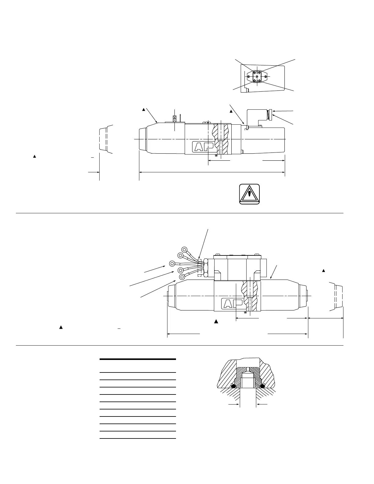
Dimensions
DG4V-3-*A(L)-(V)M-S6-U-**-60
DG4V-3-*A(L)-(Z)-(V)M-S3-FPA5W-*2-60
DG4V-3-*A(L)-(Z)-(V)M-S4-FPA5W-*2-60
DG4V-3-*A(L)-(Z)-(V)M-S5-F-*2-60
Single solenoid models with
LVDT type switch indicat-
ing when the spool is in the
spring off-set position. ISO
4400 (DIN 43650) connection
to solenoid; Pg7 connection
to switch.
Single solenoid models with
mechanical type switch moni-
toring of spool movement.
Warning
Wiring: See Electromagnetic
Compatibility (EMC) warning
note on page 8.
Port restrictor plugs
Restrictor plugs are available
for use in ports P, T, A or B.
These can be used for
restricting flow or for circuit
dampening. Restrictor plugs
are not recommended for
use above 210 bar (3000 psi)
system pressure.
Typical model codes:
DG4V-3(S)-**-M-**-**-60-P08
(0.8 mm dia orifice in port P)
DG4V-3(S)-**-M-**-**-60-
P10-A10
(1.0 mm dia orifice in ports
P and A)
RESTRICTOR PLUG
SELECTION TABLE
Code Orifice Part
diameter number
*00 Blank 694353
*03 0,30 (0.012) 694341
*06 0,60 (0.024) 694342
*08 0,80 (0.030) 694343
*10 1,00 (0.040) 694344
*13 1,30 (0.050) 694345
*15 1,50 (0.060) 694346
*20 2,00 (0.080) 694347
*23 2,30 (0.090) 694348
* = P, T, A or B, as required
n hhOrder in multiples of 25
per part number
Maximum port dia in
subplate/manifold block:
For steel and SG (ductile)
iron: 7,0 (0.3)
For gray iron: 6,5 (0.25)
Dimensions in mm(in)
248,2 (9.8) with DC solenoid
238,2 (9.4) with AC solenoid
For coil removal:
64 (2.51) DC coil
54 (2.12) AC coil
138,2 (5.44)
Location of solenoid
for RH build models
Location of switch
for RH build models
Plug (part no. 458939)
supplied with valve
Cable gland PG7:
6,0 (0.24) dia.
Pin number 2, supply +ve
Pin number 3, 0V
Pin number 1,
“normally open”
Pin number 4,
“normally closed”
For LH build (DG4V-3-*AL )
solenoid and switch locations
are reversed.
For LH build (DG4V-3-*AL )
solenoid and switch locations are reversed.
200 (7.87) with AC solenoid
210 (8.27) with DC solenoid
100 (3.94)
Location of switch and housing
for RH build models
Normally closed lead (Monitor switch)
sleeving identification color white.
Common lead (Monitor switch)
sleeving identification color black.
Normally open lead (Monitor switch)
no color identification.
Location of solenoid
for RH build models
54 (2.12)
for removal
of switch hsg.
See page 16 for details of connections
to pre-wired 5-pin receptacle for:
“S3” normally open and
“S4” normally closed.
Conduit box with leads, or
pre-wired to NFPA T3.5.29-
1980 receptacle.
M5 x 0.8-6H thread
for plug extraction