23EATON Vickers Solenoid Operated Directional Valves Product Catalog V-VLDI-MC011-E September 2008
Installation
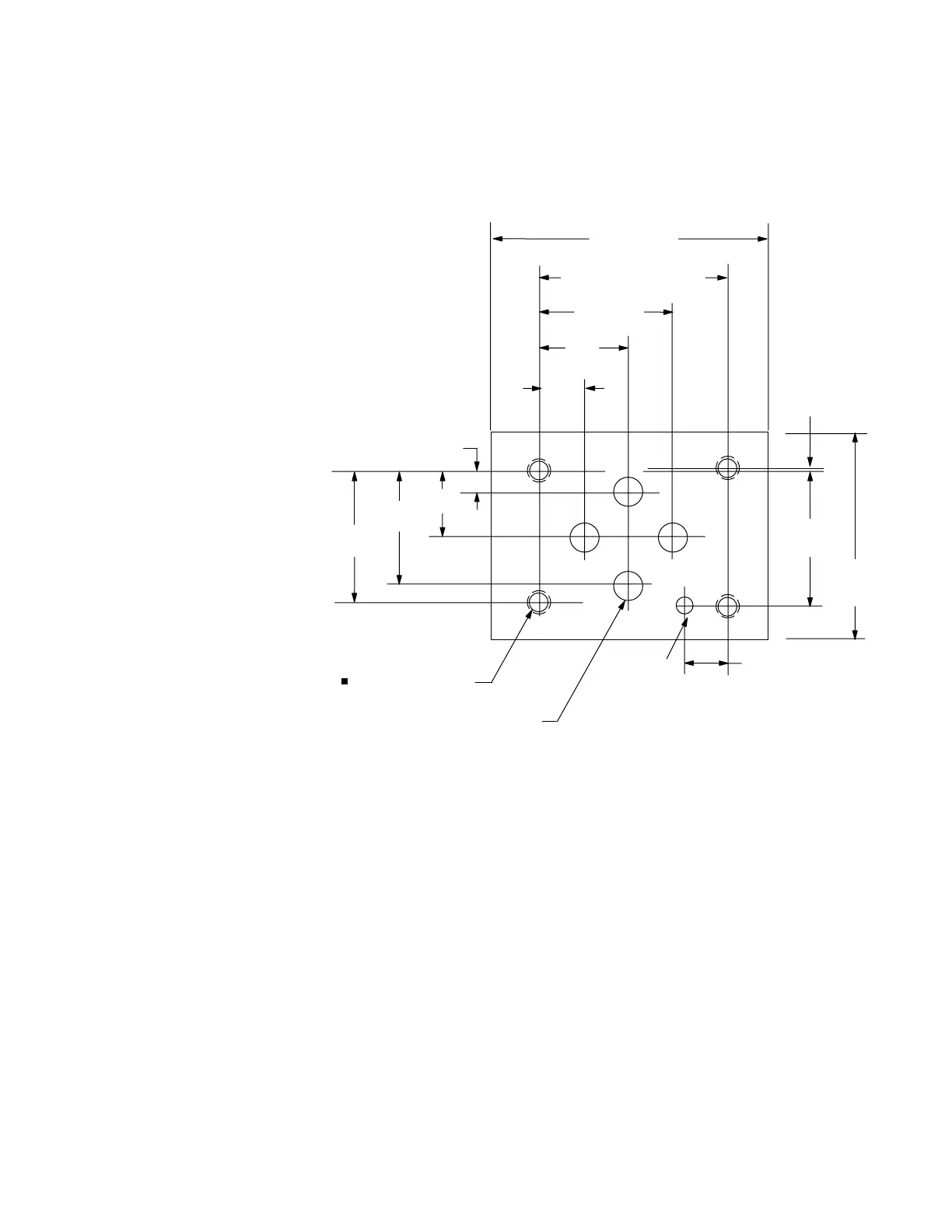
Dimensions
Mounting Surface
When a subplate is not used,
a machined pad must be
provided for mounting. The
pad must be flat within 0,01
mm per 100 mm (0.0001" per
1") and smooth within 0,8 μm
(32 μin).
The interface conforms to
ISO 4401-AB-03-4A (size 03)
plus location pin hole
ANSI/B93.7M (and NFPA)
size 03 CETOP R35H4.2-03,
plus location pin hole
DIN 24340 Form A6, plus
location pin hole
Dimensional tolerance =
±0,2 ( 0.008) except where
otherwise stated.
Prior to installing a valve,
ensure that both valve and
mounting surface are clean
and free from burrs.
s ISO 4401 gives dimensions
in mm. Inch conversions
are accurate to 0.01" unless
stated.
n #10-24 UNC-2B optional
12,7
(0.5)
40,5 ± 0,1 (1.594 ± 0.004)
31,0 ± 0,1
(1.22 ± 0.004)
25,9
(1.01)
30,2 (1.890)
21,5
(0.85)
70 (2.75) min.
48
(1.89)
min.
5,1
(0.20)
15,5
(0.61)
4 holes, M5-6H x 12,0
(0.47) min. full thread depth
4 ports Ø6,3 (0.25 dia). For all
Vickers size 3 valves this
diameter may be increased to
Ø7,5 (0.29 dia).
P
B
T
A
Ø4,0 x 4,3
min. deep
(0.16 dia x
0.17 deep)
for locating pin
31,75 ± 0,1
(1.25 ± 0.004)
0,75 ± 0,1
(0.03 ± 0.004)
7,5 (0.29)
Dimensions in mm(in).