15EATON Vickers Solenoid Operated Directional Valves Product Catalog V-VLDI-MC011-E September 2008
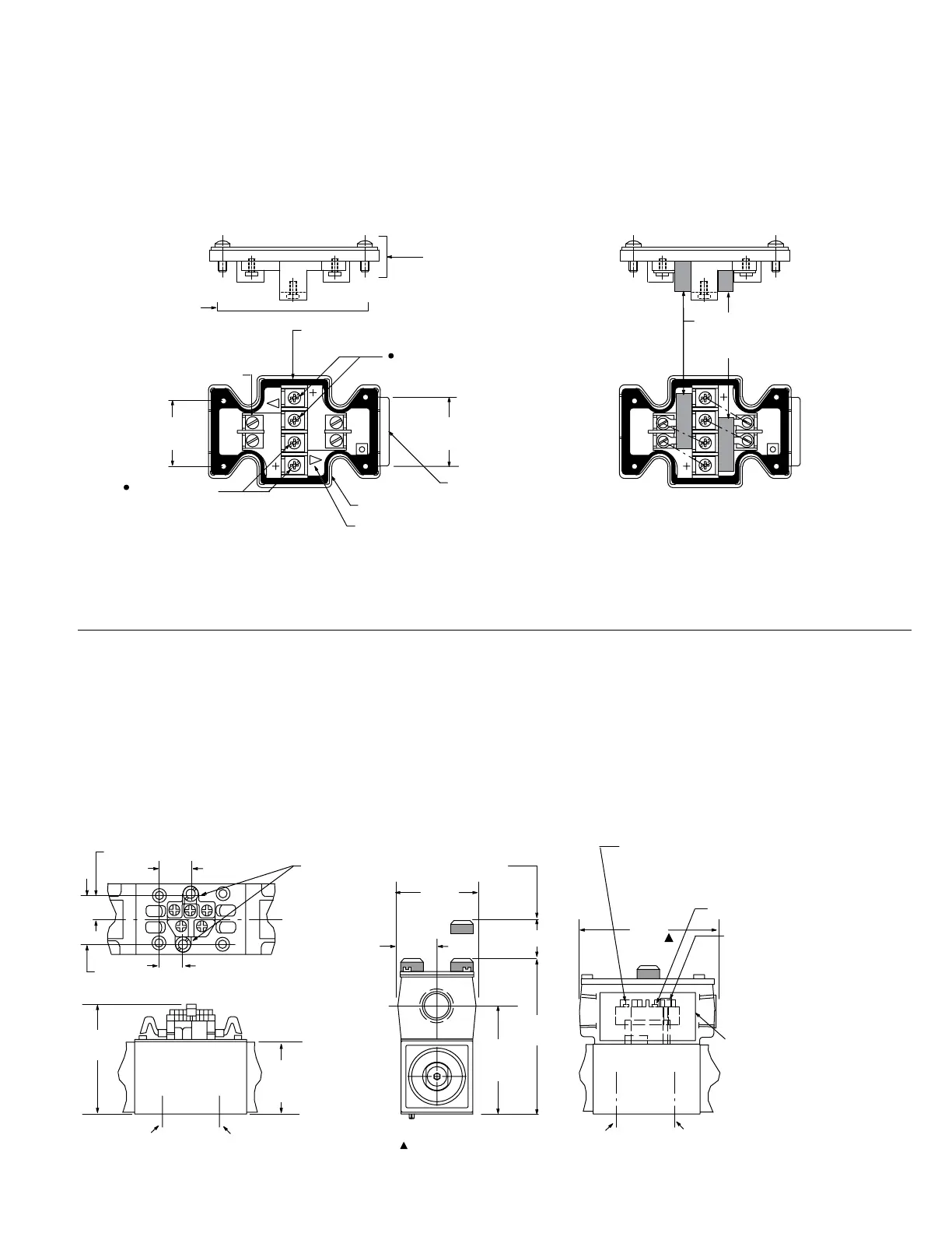
Electrical Plugs
and Connectors
Terminal strip and lights
For valves with type “F” coils.
1. For DC coils the +ve
lead(s) must be connected
to the terminal(s) marked +.
When using 3-wire incom-
ing leads to double solenoid
valves (i.e. common neutral)
the inner pair of terminals
must be interconnected.
2. For correct light indica-
tion of energized solenoid
ensure that solenoid leads
are correctly connected: light
terminals are common with
each outer pair of solenoid
terminals according to the
side with + mark.
DG4V-3(S)---FPA---60
DG4V-3(S)---FPBW---60
Eaton 2-part “Insta-Plug”
eliminates breaking electrical
inputs for valve disconnect.
A male half is pre-wired to
the valve body. The mating
plug is inside a wire housing
with external terminals for
machine wire connections.
Captive thumb screws, when
loosened, permit the wire
housing to be pulled clear of
the valve for disconnect. A
longer ground post provides
first make/last break ground
connection.
The PBW configuration com-
bines both male and female
plugs in the wiring housing for
a self-contained plug-in unit.
Optional solenoid indicator
lights are pre-wired to the
female plug. Solenoids “A”
and/or “B” are identified on
the wiring housing.
Insta-Plug
PA configuration PBW configuration
Dimensions in mm(in).
Terminal strip
(part number
890345) clips to
cover and can
be field-fitted
M3 x 0,5-6H screws
(part number 186006)
2 each end
4 terminal screws M3 x 0,5-6H
(part number 02-113355)
Connections to solenoid A
(or B, according to model type)
Connections to
solenoid B
(or A, according
to model type)
Rubber gasket
Conduit box cover and
nameplate complete with
sealing gasket and 4 screws
Anti-rotation tab ensures
correct orientation of cover
to junction box
28,50
(1.12)
30,00
(1.18)
Light assembly is held in place
by end pair of M3 screws; can
be fitted to terminal strip.
2 lenses in cover
24,0
(0.95)
71,1
(2.80)
16,25
(0.64)
47,5
(1.87)
ref.
Port A
Port B
Port A
15,5 (0.61)
20,25 (0.79)
32,50
(1.28)
M4-6H thd.
48,0
(1.89)
89,0
(3.50)
Ground connection
in terminal box
(ref.)
WARNING TAG
“Electrical power
must be
disconnected
before removing or
replacing this
receptacle”.
Customer connection solenoid at port A
end of body to female receptacle plate
Customer connection
solenoid at port B end of
body to female receptacle
plate
69,0
(2.72)
ref.
98,5
(3.88)
23,1 (0.91)
Clearance to remove
female receptacle
The conduit box dimensions used for the PA/PBW type connector are different from
those on the other “F” type coil models.
Port B