8 EATON Vickers Solenoid Operated Directional Valves Product Catalog V-VLDI-MC011-E September 2008
Operating Data
Spool Position Indicator
Models, high performance
valve DG4V-3 ONLY
Spool/spring arrangement
types 0A (L), 2A(L), 22A(L)
DC model type “S6”
(see page 14 for Installation
Dimension)
This product has been
designed and tested to
meet specific standards out-
lined in the European Electro-
magnetic Compatibility.
Directive (EMC) 89/336/EEC,
amended by 91/263/EEC,
92/31/EEC and 93/68/EEC,
article 5. For instructions on
installation requirements to
achieve effective protection
levels see this leaflet and the
Installation Wiring Practices
for Eaton's Vickers
®
Electronic
Products leaflet 2468. Wiring
practices relevant to this
Directive are indicated by
Electromagnetic
Compatibility (EMC).
Input:
Supply voltage 10 to 35V DC inclusive of a maximum 4V pk-to-pk ripple
Current, switch open 5 mA
Current, switch closed 255 mA
Output:
Voltage 1V below input at maximum load
Maximum continuous current 250 mA
Maximum load impedance 136Ω at maximum input volts
Maximum switching frequency 10 Hz
Plug connections:
Pin 1 (output 1) Normally open (ie. not connected to pin 3)
Pin 2 Supply +ve
Pin 3 0V
Pin 4 (output 2) Normally closed (ie.connected to pin 3)
Switching point Within the spool spring offset condition •
Connector Pg7 plug (supplied with valve)
Protection Overload and short-circuit protected; self re-setting.
IEC 144 class IP65 with connector correctly fitted.
• Factory setting ensures this condition under all combinations of manufacturing tolerance and of temperature drift (see “Temperature Limits”).
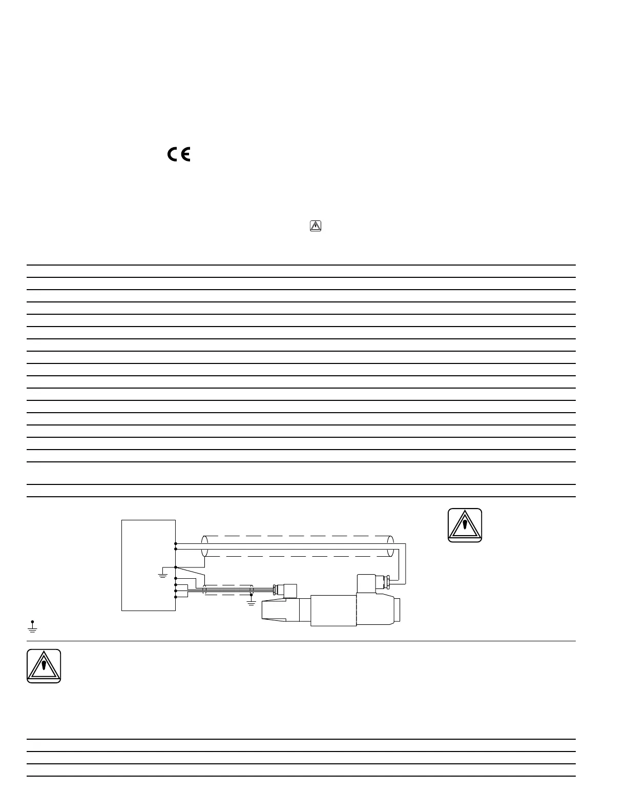
Wiring Connections
Warning
All power must be switched
off before connecting or
disconnecting any plugs
WARNING: Electromagnetic Compatibility (EMC)
It is necessary to ensure that the unit is wired up in accordance with the connection arrangements shown above.
For effective protection the user’s electrical cabinet, the valve subplate or manifold and the cable screens should be
connected to efficient ground points.
In all cases both valve and cable should be kept as far away as possible from any sources of electromagnetic
radiation such as cables carrying heavy current, relays and certain kinds of portable radio transmitters, etc. Difficult
environments could mean that extra screening may be necessary to avoid the interference.
Micro-switch type “S3”, “S4” and “S5”
Voltage 250V maximum 50/60 Hz
Maximum current 5A
Electric
panel
Customer’s protective ground connection
SolenoidLVDT