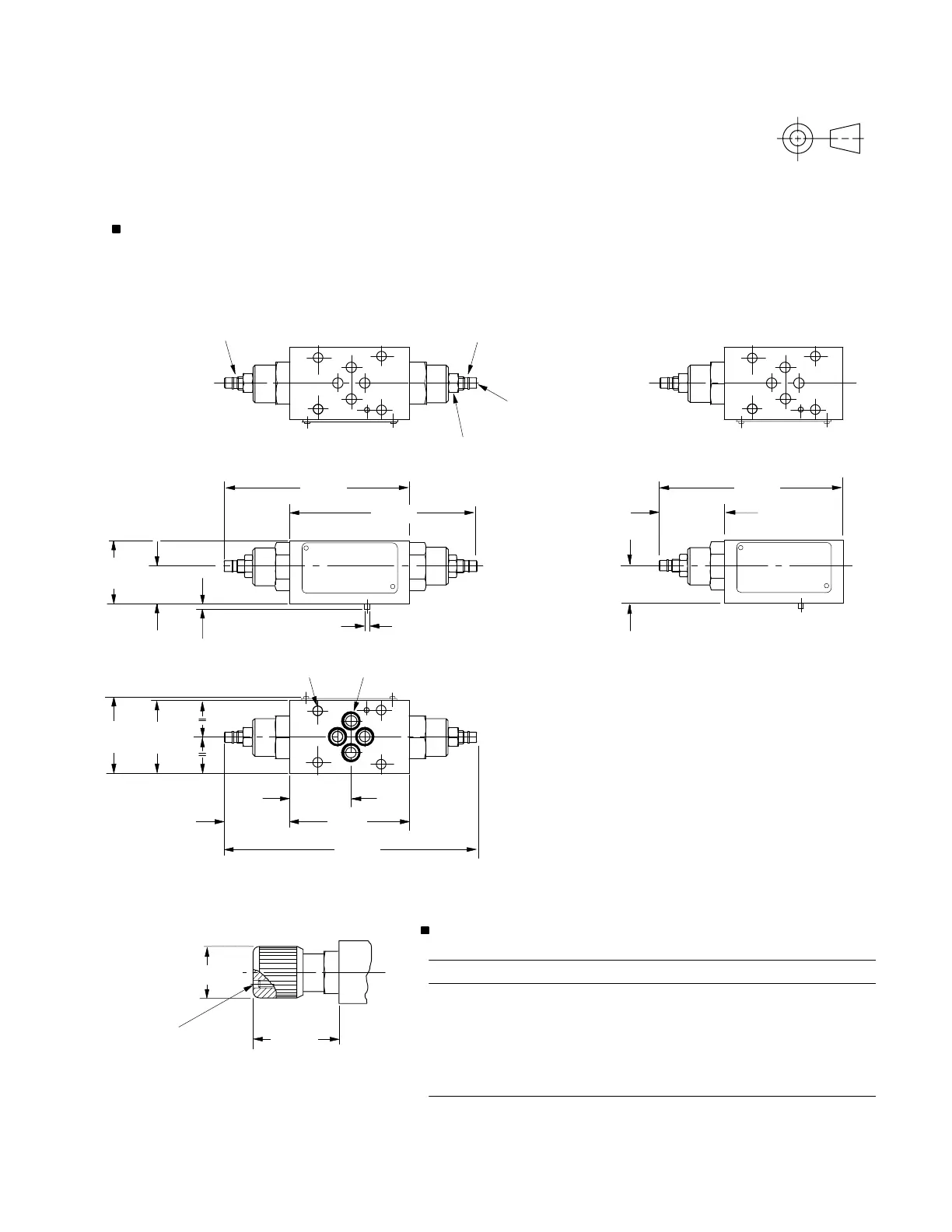
DGMFN-3-X-***(-***)-4*
DGMFN-3-Y-***(-***)-4*
DGMFN-3-Z-***-4*
Models with type W adjuster
To adjust valve setting, slacken off locknut and turn
screw . Re-tighten locknut after completing
adjustment.
Turn clockwise to decrease flow (increase restriction);
counter-clockwise to increase flow (reduce restriction).
Model A B C D E
DGMFN-3-X-A*W-4* 121 (4.76) –––16,75 (0.7)
DGMFN-3-X-A*W-B*W-4* ––167 (6.6) – 16,75 (0.7)
DGMFN-3-X-B*W-4* – 122 (4.8) ––16,75 (0.7)
DGMFN-3-Y-A*W-4* 121 (4.76) –––23,25 (0.9)
DGMFN-3-Y-A*W-B*W-4* ––167 (6.6) – 23,25 (0.9)
DGMFN-3-Y-B*W-4* – 122 (4.8) ––23,25 (0.9)
DGMFN-3-Z-P*W-4* –––123 (4.8) 16,75 (0.7)
DGMFN-3-Z-T*W-4* –––123 (4.8) 23,25 (0.9)
Installation Dimensions in mm (inches)
A
P
B
T
A
P
B
T
A
P
B
T
Line B or line P adjustment
(according to model type)
39 (1.54)
76 (3)
C max.
45 (1.8)
max.
47,6
(1.87)
46
(1.8)
4 off “O” seals supplied for this interface4 holes through: Ø5,3 (0.21 dia)
A max.
4 (
5
/
32
) A/F hex. socket
40
(1.57)
3,5 (0.14)
Ø3 (0.12 dia)
E max.
12,7 (
1
/
2
) A/F hex. locknut .
Torque to 25-30 Nm (18-22 lbf ft)
Line A or line T adjustment
(according to model type)
B max.
D max.
47 (1.85)
max.
E max.
56 (2.2)
max.
Ø32 (1.26 dia)
M4 locking screw
2 (
5
/
64
) A/F hex. socket
Type H adjuster
21
 Loading...