Relief Valves
DGMC-3-4*
DGMC2-3-4*
General Description
These two-stage adjustable pressure
relief valves limit the maximum pressure
in the line(s) controlled by the integral
relief valve elements.
Pressure adjustment options of control
knob (with or without keylock) or
screw/locknut design are available. The
two-stage operation is basically identical
to long-established balanced piston
valves, described in detail in Vickers
Industrial hydraulics manual.
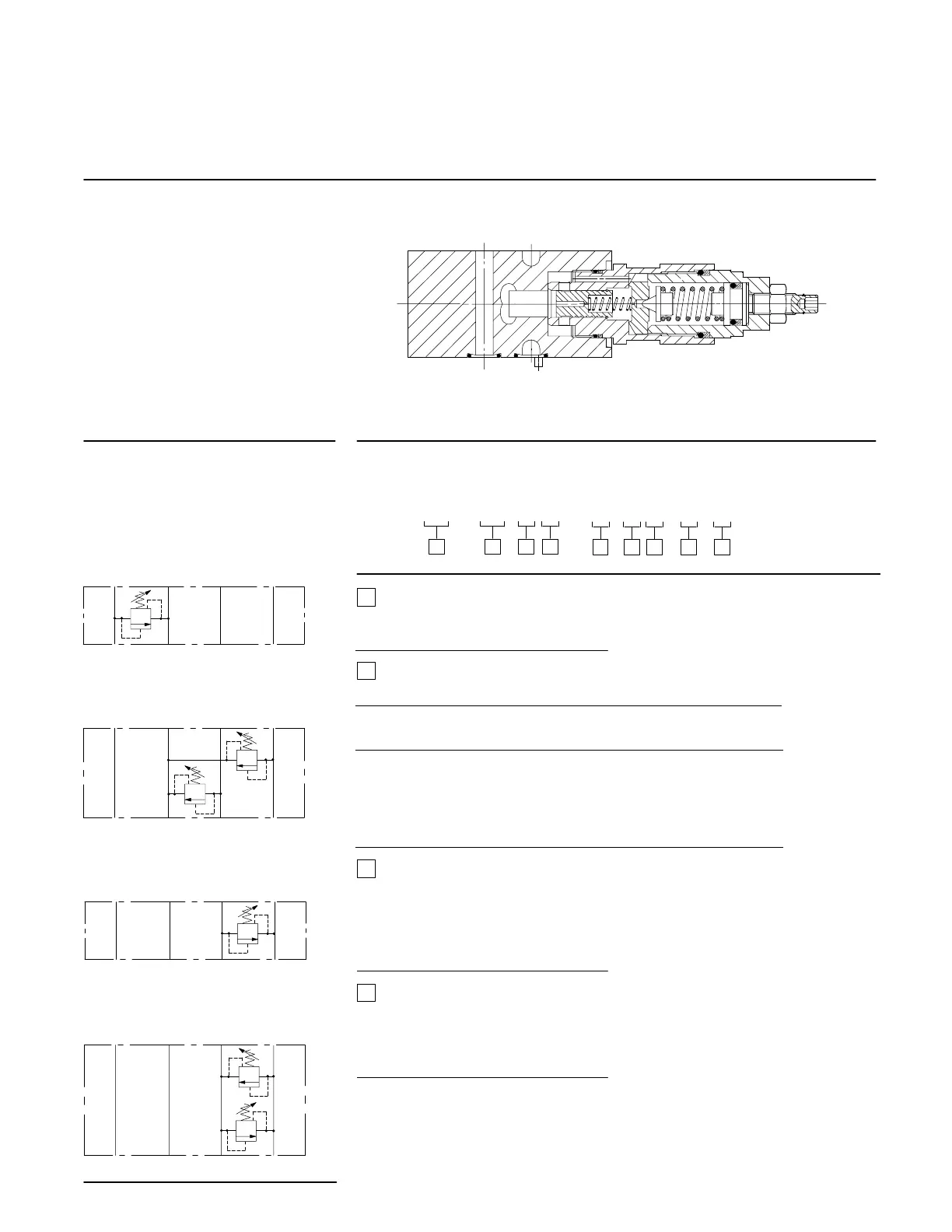
Typical Section
Functional Symbols
For simplicity these two-stage valves are
represented as single-stage models
PTBA
DGMC-3-PT-**
DGMC2-3-AT-**-BT-**
DGMC-3-BA-**
DGMC2-3-AB-**-BA-**
PTBA
PTBA
PTBA
Model Code for Relief Valves
DGMC(2)-3- ** - * (-B* - * * )- * - 4*
1 2
*
3 4 5 6 7 8 9
1
Type
2 = Dual relief function
Omit for single relief function
First function
Single relief, or first line of dual models
Code Pressure Discharge Usage
limited in into
PT P T Single only
AB A B Single, or dual with BA
BA B A Single only
AT A T Single, or dual with BT
BT B T Single only
2
3
4
Pressure adjustment range, first
function
A = 3-50 bar (43.5-725 psi)
B = 3-100 bar (43.5-1450 psi)
C = 10-200 bar (145-2900 psi)
G = 50-315 bar (725-4500 psi)
Pressure adjustment/ locking
method, first function
H = Handknob
K = Micrometer with keylock
W = Screw and locknut
5