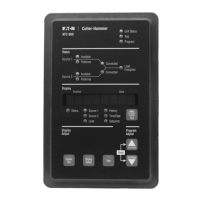
Figure 1. ATC-600 Operator Panel.
1. ATC-600 Faceplate (UV Resistant)
2. Operational Mode LEDs (highlighting ATC-600’s
present operational condition)
3. System Status Mimic Bus (easy to read and under-
stand LED type)
4. Display Window (easy to read monitored parameters,
setpoints and messages)
5. Display LEDs (seven LEDs to identify the Display Win-
dow Information)
6. Help Pushbutton (provides English language help
information in any operational mode)
7. Increase/Decrease Pushbuttons (used individually,
pushbuttons move displayed information/setting up or
down through all possibilities – used simultaneously
while viewing historical logged values, values reset to
zero)
8. Step Pushbutton (used to step through different avail-
able information within the category being displayed)
9. Display Select Pushbutton (used to move the display
through the categories represented by the 7 LEDs
under the display)
10. Engine Test Pushbutton (pushed and released twice
to initiate a self test in Run or Program Modes

 Loading...