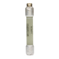
2. Wire brush all terminals, connectors and electrical
conductors.
3. Apply an oxide inhibitor prior to making electrical
connections.
4. Insert Companion II fuse and conductors into
connectors and tighten.
•
Maintain a minimum of 14" of clearance from the
source leads to the lower end of the Companion II
fuse and related energized hardware of the cutout.
•
When mounting the Companion II fuse in the upper
terminal of a fused cutout, replace expendable caps
with solid caps.
•
Make sure vents from the cutout fuse holder will
not direct expulsion gases towards the Companion
II fuse.
•
Apply minimal cantilever load to the Companion II
fuse.
5. Re-energize the line using approved safety procedures.
Figure 4. Companion II fuse mounted from a bail
attached to the overhead line.
ARRESTER
COMPANION II
FUSE
CUTOUT FUSE
LINK IN FUSE-
HOLDER
TRANSFORMER
PRIMARY
BUSHING
Figure 2. Companion II fuse mounted on the source side of
the cutout.
ARRESTER
COMPANION II
FUSE
CUTOUT FUSE
LINK IN FUSE-
HOLDER
TRANSFORMER
PRIMARY
BUSHING
Figure 3. Companion II fuse mounted on the load side
of the cutout.
ARRESTER
COMPANION II
FUSE
CUTOUT FUSE
LINK IN FUSE-
HOLDER
TRANSFORMER
PRIMARY
BUSHING
3
COMPANION II BACK-UP CURRENT-LIMITING FUSE INSTALLATION INSTRUCTIONS MN132009EN

 Loading...


