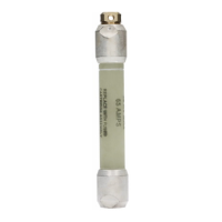
Fuse application
When selecting the proper size Companion II fuse for each
installation, continuous current, voltage rating, and both
upstream and downstream coordination should be taken
into account.
The Companion II fuse rating indicates the largest Type K
fuse link that properly coordinates with the fuse. Select a
Companion II fuse size that is greater than or equal to the
Type K fuse link size used in the cutout at that location.
For fuse links other than Type K links, select the proper
Companion II fuse based on Table 1. For fuse links not
included in this table, contact your Eaton representative.
The voltage ratings recommended for the Companion II fuse
on most commonly encountered distribution systems are
listed in Table 2.
For further information concerning the coordination of the
Companion II fuse, see Catalog CA132021EN Companion
II Back-up Current-Limiting Fuse or contact your Eaton
representative.
*
Installation procedure
Figures 2 through 7 show typical installations of the
Companion II fuse. It may be installed on the source side
(Figure 2) or load side (Figure 3) of a distribution cutout.
It may be hung from a bail attached to the overhead line
(Figure 4), or it may be attached directly to the transformer
bushing (Figures 5 or 6).
The lightning protection is connected to the line side of the
Companion II fuse and the distribution cutout.
Installation of the Companion II fuse
Once the end terminals have been installed on the
Companion II fuse (refer to “Installation of Terminal
Options” on page 4):
1. Remove fuseholder from distribution cutout using a
hookstick.
•
Always use a loadbreak device to open an energized
cutout. Follow manufacturer’s recommendations for
operation of loadbreak tools or cutouts which are
designed to break load current.
Table 1. Companion II Fuse-Fuse Link Coordination
Companion II
Fuse Rating
Coordinated With Fuse Links Up Through
Type K Type T
Edison™
Type N
Edison
Type S
Edison
Type H
Edison
Type D
12K 12 8 20 5 8 1.5
25K 25 15 30 7 8 20
40K 40 20 50 15 8 20
Kearney™
Type X™
Kearney
Type
QA™
Kearney
Type
200™
Kearney
Type KS™
12K 2.5 15 10 3
25K 10 30 20 7
40K 15 50 30 15
Table 2. Companion II Fuse Voltage Application
System Voltage (kV)
Recommended Companion II
Rating (kV)
Nominal Maximum
Four-Wire
Multi-grounded
Neutral Delta
2.4 2.54 – 8.3
2.4/4.16 2.54/4.4 8.3 –
4.16 4.4 – 8.3
4.8 5.1 – 8.3
4.8/8.32 5.1/8.8 8.3 –
6.9 7.26 – 8.3
6.93/12 7.3/12.7 8.3 –
7.2 7.62 – 8.3
7.62/12.47 7.62/13.2 8.3 –
7.62 8.1 – 8.3
7.62/13.2 8.1/14.0 8.3 –
7.97 8.4 – 8.3
7.97/13.8 8.4/14.5 8.3 –
8.32 8.8 – 8.3
8.32/14.4 8.8/15.2 8.3 –
12/20.8 12.7/22 15.5 –
12.47 13.2* – 8.3**
13.2/22.9 14/24.2 15.5 –
13.2 14* – 8.3**
13.8 14.5* – 8.3**
14.4/24.9 15.2/26.4 15.5 –
14.4 15.2 – 8.3**
19.9/34.5 21.1/36.5 23 –
34.5 36.5* – 23**
46 48.3* – 23**
* Fuse voltage ratings recommended for these systems are based on
simultaneous operation of the Companion II fuses for high current faults.
** For single-phase applications on delta systems, one fuse of this rating is
required in each phase.
WARNING
When installing on hot lines, be sure to observe proper
clearances between live and de-energized parts. Use
only approved safety practices.
2
COMPANION II BACK-UP CURRENT-LIMITING FUSE INSTALLATION INSTRUCTIONS MN132009EN

 Loading...


